2
\$\begingroup\$

We have the BJT transistor in the figure.
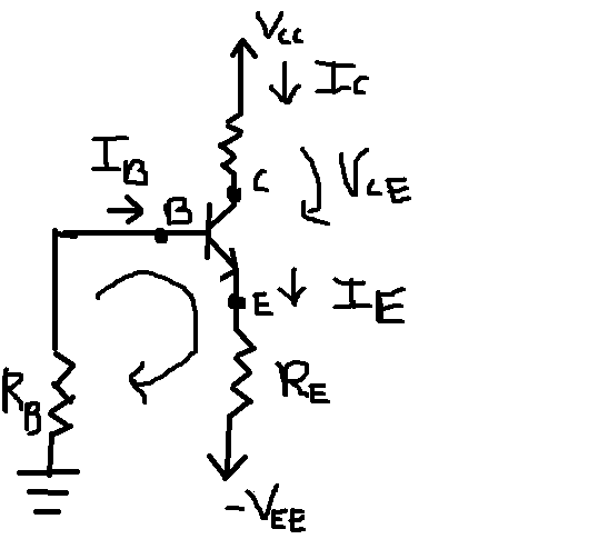
enter image description here

I have to do the DC analysis of the circuit, then draw the common base transistor scheme of the circuit. I know the values of \$V_{cc}\$, \$V_{be}\$, \$R_c\$, \$R_e\$ and \$β\$.

So I apply KVL just like I have pointed it in the figure.

$$I_BR_B=V_{BE}+I_ER_E-V_{EE}$$

then we have

$$V_{EE}-V_{BE}=I_ER_E+I_BR_B$$

then

$$V_{EE}-V_{BE}=I_ER_E+\frac{I_E}{β+1}R_B$$

Definitely we find that

$$I_E=\frac{V_{EE}-V_{BE}}{\dfrac{R_B}{β+1}+R_E}$$

Problem is, I don't have the value of \$V_{EE}\$. How do I do the DC analysis now? Also can you please show me the scheme of the common base transistor in this case?

\$\endgroup\$
3
  • \$\begingroup\$ Just for clarification: The circuit does not show any signal input nor output. Hence, all you can do is to perform a calculation of the dc operating point. The question if it is common emitter or common base or common collector depends on these signal nodes (and the location of capacitors, if any). \$\endgroup\$
    – LvW
    Commented Sep 6, 2014 at 15:36
  • \$\begingroup\$ Thank you..can I find Ic by using Vcc/Rc? \$\endgroup\$ Commented Sep 6, 2014 at 17:43
  • \$\begingroup\$ Of course, not! Rc is not the only component connected to Vcc. The BJT is to be considered as a current source which produces Ic - indpendent (as a first approach9 on Vcc. But Ic strongly depends on Vee. \$\endgroup\$
    – LvW
    Commented Sep 7, 2014 at 9:26

1 Answer 1

2
\$\begingroup\$

There is a sign error in the 1st equation. The node voltage at the base is

$$V_B = -I_B\cdot R_B$$

so the correct KVL equation is:

$$-I_B\cdot R_B = V_{BE} + I_E \cdot R_E + \left(-V_{EE}\right)$$

The 2nd equation does not have the sign error.

If you do not have the value for \$V_{EE}\$, all you can do is provide the answer in terms of \$V_{EE}\$. Deriving one of the DC bias equations, as you have done, may be all that is required.

Also can you please show me the scheme of the common base transistor in this case?

It isn't clear to me what you're asking for since the canonical common base circuit schematic can be found in almost any transistor circuits textbook and is easily found with a Google search.

\$\endgroup\$
3
  • \$\begingroup\$ I wanted to know how to use Vcc and Rc since I have their values... \$\endgroup\$ Commented Sep 6, 2014 at 15:17
  • \$\begingroup\$ @user3543012, \$V_{CC}\$ and \$R_C\$ determine \$V_C\$, the quiescent collector voltage. The quiescent emitter current \$I_E\$, assuming the transistor is biased in the active region, is (ignoring the Early effect) independent of \$V_{CC}\$ and \$R_C\$. \$\endgroup\$ Commented Sep 6, 2014 at 16:11
  • \$\begingroup\$ I rather would say: Vcc and Rc and Ic determine the voltage Vc. \$\endgroup\$
    – LvW
    Commented Sep 7, 2014 at 10:46

Your Answer

By clicking “Post Your Answer”, you agree to our terms of service and acknowledge you have read our privacy policy.

Not the answer you're looking for? Browse other questions tagged or ask your own question.