0
\$\begingroup\$

I have a load box I use to test and burn in analog audio power amplifiers. Each load box is tailored for a specific amplifier circuit and for one of the load boxes I would like to add an LED that starts to illuminate when a certain output voltage is reached and get brighter as the output signal gets larger. The amplifier in question can produce signals as high as 200V peak to peak and drive loads as low as 4 ohms. I am running into an issue:

The output signal needs to be stepped down so that I can use an opamp based LED driver circuit running on +/-15V. The problem is.. a resistive voltage divider would alter the impedance seen by the amplifier output as it would be in parallel with the load resistor.

Is there any way to implement this LED without altering the overall load impedance?

\$\endgroup\$
4
  • \$\begingroup\$ How accurate is the 4 ohm load? \$\endgroup\$
    – Andy aka
    Commented Sep 18, 2014 at 16:56
  • \$\begingroup\$ It is not critical. It's a simple heatsinked power resistor that currently measures 4.21 ohm. If I can get away with using a resistive divider that only alters the impedance minimally then that is ideal. \$\endgroup\$
    – disorder
    Commented Sep 18, 2014 at 17:26
  • \$\begingroup\$ Well if you put a 10k resistor in parallel with your 4.21 ohm resistor, the net resistance would drop to 4.208 ohms - if you don't see that as a problem I certainly don't \$\endgroup\$
    – Andy aka
    Commented Sep 18, 2014 at 21:21
  • \$\begingroup\$ What's the "certain output voltage" at which you'd like the LED to start illuminating, and what would you like the ratio between its minimum and maximum brightness to be? \$\endgroup\$
    – EM Fields
    Commented Sep 19, 2014 at 11:41

2 Answers 2

1
\$\begingroup\$

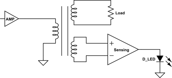
schematic

simulate this circuit – Schematic created using CircuitLab

It can be implemented by a transformer with a primary coil impedance equal to the load impedance that the amplifier needs, and two secondary windings, one for loading and one for powering the LED indicator circuit.

\$\endgroup\$
1
  • \$\begingroup\$ This is a good straightforward solution, however I would need a transfo capable of handling the high wattage and I don't have the money or space for it in the load box enclosure. \$\endgroup\$
    – disorder
    Commented Sep 18, 2014 at 17:46
0
\$\begingroup\$

If you has a voltage divider that totals about 10K ohms (e. g. one 10K resistor and one 500 ohm resistor), you'll get a hair under 10V out with 200V in. This will guarantee not to overdrive your opamp. Meanwhile, this, in parallel with your 4.21 ohm power resistor will still keep the load virtually unchanged.

\$\endgroup\$

Your Answer

By clicking “Post Your Answer”, you agree to our terms of service and acknowledge you have read our privacy policy.

Not the answer you're looking for? Browse other questions tagged or ask your own question.