7
\$\begingroup\$

Ok.....i've been trying to understand something (and trust me, to most people it's a VERY newbish question)

So I see people all the time "multiplexing" LEDS. using just a few Pins.

Lets say for an Arduino that has..... 5 I/O pins for example, apparently this can control 20 LEDS (or so i've been told) using Multiplexing...but.....what Im confused about is that this is all controlled by 5 pins. Maybe im getting Multiplexing wrong but how exactly does this happen?

Also as iv'e been reading assembly tutorials for the AVR I notice that each Port has 3 registers, PORTB, DDRB and PINB, do these correspond with LOW/HIGH/OFF.....or is this entirely unrelated?

I guess I don't understand the whole idea of Multiplexing, I've read tutorials.....but I don't understand exactly how/why you hook them up, and for that matter where (and how much) to use resistors for, I know using certain combinations of High/Low/Input you can achieve a pretty awesome LED matrix. but How do I determine this. Im sure you would have to use transitors though right?

Sorry for the confusing question, it's even harder to ASk the question when Im not very sure about it.

edit: Also I understand Shift Registers/Multiplexing (at least somewhat) in terms of "Truth tables" but I dont understand actually how to implement it. Maybe anyone could recommend a book on using Transistors and the like with Electronics, since some of the basic books really only go over Capacitors/Resistors

\$\endgroup\$

3 Answers 3

6
\$\begingroup\$

I started writing about demultiplexers and calling the multiplexers, so the error should now be fixed. What you need to easily control multiple LEDs are demultiplexers, or use of multiplexers in reverse.

Here's a simple version: Imagine you have a telephone. The telephone is (in our simple world) connected to a switchboard and the board is connected to other telephones.

When you dial a number, the board recognizes it and connects your telephone to another telephone and that's how connection is made. You only need one telephone and one switchboard to connect that one telephone to multiple other telephones.

Demultiplexers work in a similar way, except here the data and address lines are separated.

So you have a hardware demultiplexer. It has address pins, input pin and output pins.

Your microcontroller also has output pins. In the LED example, you can connect one output of the microcontroller to input of the demultiplexer. Using that one pin, you can control one LED at a time. If you connect the other output pins of the microcontroler to the demultiplexer, you can set the address. To get back to out telephone example, you use the microcontroller output pins connected to demultiplexer address pins to dial a number. So you send a signal to the demultiplexer and the signal is actually a binary number. The output pin of the demultiplexer with that number is then connected to the demultiplexer's input pin and you can send data from the microcontroller to the device connected to demultiplexer's output. This itself isn't very useful, because the demultiplexer is then a fifth wheel.

Here comes the interesting part: When you're done using the device connected to that particular output, you can the use address pins to select another output pin with another device connected to it. This way, we get a simple switch, so we can select the device to which the microcontroller will communicate.

Now let's get to the LED example. You have a microcontroller with 5 output pins. Let's say that you have a demultiplexer with 4 address pins, one input pin and 16 output pins (Mo0 to Mo15). Let's also say that you want to control 16 LEDs. So you connect each LED to the output pin of the demultiplexer and you connect 4 output pins (Here called A0-A3) of the Arduino to the address pins of the demultiplexer. That leaves one pin for the demultiplexer input pin (here called Ao) .

Now let's say that you want to light up a LED. You can just power up the Ao pin. In this case, the demultiplexer will read the signal sent by the A0-A3 pins. Since they are low, it will interpret that as 0000. That is the number of pin Mo0, so it will connect Mo0 to Ao. Now let's say you want to turn on another diode. You can do that by setting A0 pin to high, so you'll get 0001 and demultiplexer will connect pins Ao and Mo1. This way, you can connect Ao to any of the Mo pins.

OK, that's nice, but how do you control all LEDs at the same time? Well, you don't. Instead, you'll exploit limits of human perception. If you turn an LED on and off fast enough, people won't notice.

For that you'll need a program which will cycle through selected output pins at a certain rate. The program should count up the A pins like binary numbers and that way you'll select which LED to control at each particular moment.

As for the registers you mentioned. Well, they are related, but at a different level. My advice is to learn first how to control one LED. After that learn how to control several LEDs connected to same port. When you learn that, you'll know how to set address pins for a demultiplexer high or low (it's same as turning on or off an LED) and since you already know how to control an LED, you'll be able to control the currently selected LED.

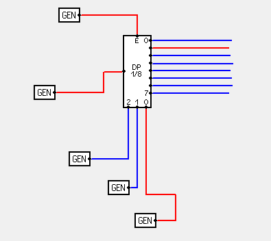
Here's a picture of a demultiplexer. The GEN on the left is input signal. The GEN on the top controls if the multiplexer is on or off. In a real world project, you'd do this using power connectors. The 3 GENs on the bottom control address pins and on the right are output signals. When the address lines are low, output number 0 is selected.
pin 0

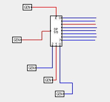
Here we have pin 1 selected:

pin 1

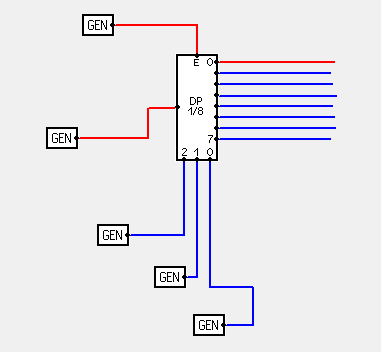
Here we have pin 2 selected:

pin 2

And finally here we have pin 3 selected:
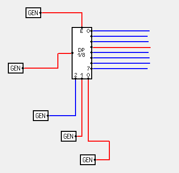
pin 3

Same results should be obtainable using a multiplexer and connecting the microcontroller's output to multiplexer's output and using multiplexer's input pins as output. Of course, before doing that datasheet should be checked to see if such thing is possible.

I just now noticed that you mentioned resistors. As I mentioned, before controlling large number of LEDs, first learn to control a single LED.

This one depends on microcontroller, but for AVR, when you set a pin to high state, it will be set to 5 V. Also maximum current through each pin should be limited. I used for example ATmega 162 and it can provide up to 200 mA for all pins and up to 20 mA for each pin. Another important thing is the LED current use. Different types of LEDs need different amounts of current to achieve maximum brightness. The second important characteristic of a LED is it's voltage drop. I used for example a 20 mA, 3.6 V LED. In this case, I need to limit current to under 20 mA. To do that, I used a resistor. There's a nice calculator here, which will tell you what type of resistor to get for the LED. Also, when choosing the LED current, keep in mind that you're looking for the lower of the two supplied currents. You shouldn't exceed current of microcontroller pin and you shouldn't exceed current of the LED itself.

\$\endgroup\$
4
  • \$\begingroup\$ There's a serious mistake in this post, fixing it now. \$\endgroup\$
    – AndrejaKo
    Commented Apr 14, 2011 at 20:45
  • \$\begingroup\$ Should be fixed now. \$\endgroup\$
    – AndrejaKo
    Commented Apr 14, 2011 at 20:58
  • \$\begingroup\$ Dang, Nice explanation. But then why do people always call it "multiplexers" instead of demultiplexers when controlling LEDS, im assuming you can do both but de-multi's are easier? \$\endgroup\$
    – user3073
    Commented Apr 14, 2011 at 21:25
  • \$\begingroup\$ @Sauron I'm not sure. Maybe multiplexers can be used in both roles so in reality only multiplexers are manufactured? \$\endgroup\$
    – AndrejaKo
    Commented Apr 14, 2011 at 21:28
1
\$\begingroup\$

The act of multiplexing consists of taking a number of signals and combining them into one. The act of demultiplexing consists of taking one multiplexed signal and reconstituting the multiple outputs.

As a simple mechanical analogy, suppose there are sixteen switches that need to control sixteen lights some distance away, but one doesn't want to run sixteen wires. One approach would be to rig a motor/commutator arrangement that would connect one wire (the "data" wire) to one of the sixteen switches, and output on four other wires a 1/0 pattern indicating which of the sixteen switches was selected. At the other end, one could use the four "counting" wires along with some relays to connect the "data" wire to one of sixteen lightbulbs. Sixteen wires have now been reduced to five.

Note that the signal sent on the "counting" wires doesn't change with what switches are enabled and disabled. One could omit the four wires between the sender and receiver if there were other ways of keeping them in sync. For example, one could arrange the commutator wheel so that it would always have a gap between the lights, but would send a long "fixed" pulse every revolution. The receiving end could have a mechanism to look for that long pulse and make sure its motor was positioned suitably.

When lights are multiplexed in this fashion, it's possible for the sender to communicate any combination of lights to the receiver, but multiplexing effectively delays transmission. When a light is switched on, the receiver won't know about it until the multiplexing wheel comes around. In some situations, speed is essential but it's not important to communicate the state of all the switches--just the highest-numbered one that's enabled.

To handle that scenario, one could have one wire which indicates whether any of the switches have been turned on, and four wires to indicate which of the sixteen switches is the highest-numbered one that's turned on. At the receiving end, relays could light one of sixteen lamps based upon the combination of signals on the incoming wires. This system is not called "multiplexing", but "encoding". The device to detect which of the sixteen inputs is the highest one turned on and set the outputs accordingly is an "encoder"; the device to light the appropriate lamp is a "decoder".

Note that the decoder is in fact identical to the original relay-based demultiplexer; what differs is how it's used. In the original system the pattern sent on the selector wires was fixed and the real information was sent in on the "data" wire. Here, the data wire simply serves as a master enable, and the real information is sent on the selector wires (actually, if there were fifteen switches rather than sixteen, one could omit the selector wire, but in many cases a master enable is a very useful thing to have; among other things, it may be hard to ensure that signals on all the other wires are processed identically, but it would be much easier to ensure that the master-enable would arrive last).

There's one other scenario that's worth mentioning: the intended receiver of the data might want to be able to find out the status of any particular switch instantly, but only be interested in one at a time. In this scenario, the receiver of the data would supply four select wires to the sender, and the sender would use some relays to connect one of the sixteen switches to the return data wire. The sender is a effectively multiplexer (combining many independent signals into one); the receiver can do with the information what he wants.

The multiplxer (take a number of data inputs, plus a selector input) is so called because that is by far its most common use. Whether the selection of inputs is occurring at some regular interval, or if in practice the recipient of the data is interested in one particular input far more than any other, the multiplexer combines many inputs into one. If a microprocessor is used to poll multiple inputs and store the results in different places, the microprocessor would be acting as a demultiplexer.

On the flip side, a device to enable one of some number of outputs based upon a selector and master-enable input could be used as a demultiplexer, but such devices are far more often used for decoding a binary-coded selector signal into a one-hot output. The processor outputs on the select wires an indicator of which signal it wants to be active, and the decoder's job is to make that happen. In a processor-controlled multiplexed grid of LEDs, the CPU effectively multiplexes the LED data and the LEDs themselves serve as demultiplexers (if 16 LEDs have a processor pin wired as a common cathode, and the anodes of the LEDs are wired to a decoder, each LED will individually either convey or not convey the state of the processor line, based upon whether its row wire is active).

The only time one typically sees the term "demultiplexer" used is with analog signals. If a device connects an analog signal to one of sixteen outputs, it's usually clear that the signal itself is what's interesting, rather than the selection of the output.

\$\endgroup\$
1
\$\begingroup\$

I suppose a person could drive a bunch of LEDs using multiplexer or demultiplexer or address decoder chips, but that arrangement seems pretty rare.

People with big square grids of LEDs generally drive then in a "LED matrix" arrangement. Alas, the "LED matrix" arrangement is a bit difficult to explain -- perhaps the pictures will help at arduino 3x3 LED matrix ?

People with one long line of LEDs often drive them using shift registers. Those are much easier to understand.

Yes, DDRB and PORTB are used to drive LOW/HIGH/OFF of the 8 pins of port B. The PINB is used to read the current state of those pins. If you are using Arduino, you may find it simpler to use the pinMode() and digitalWrite() library functions.

\$\endgroup\$

Your Answer

By clicking “Post Your Answer”, you agree to our terms of service and acknowledge you have read our privacy policy.