3
\$\begingroup\$

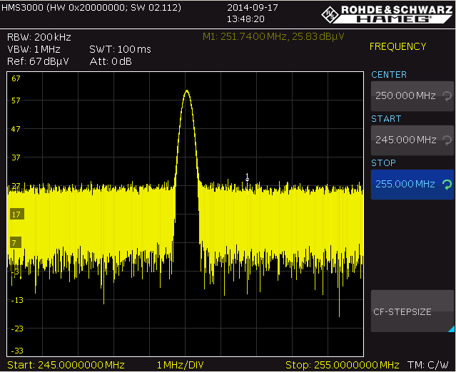
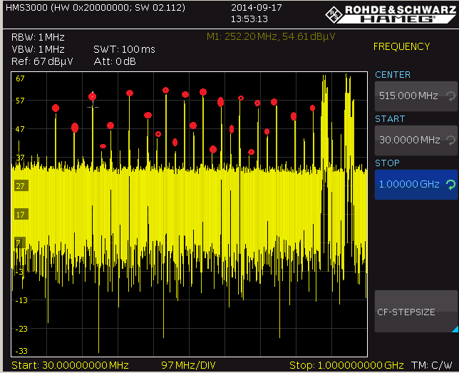
My PCB has been suffering with 25 MHz and 50 MHz harmonics radiation emission.

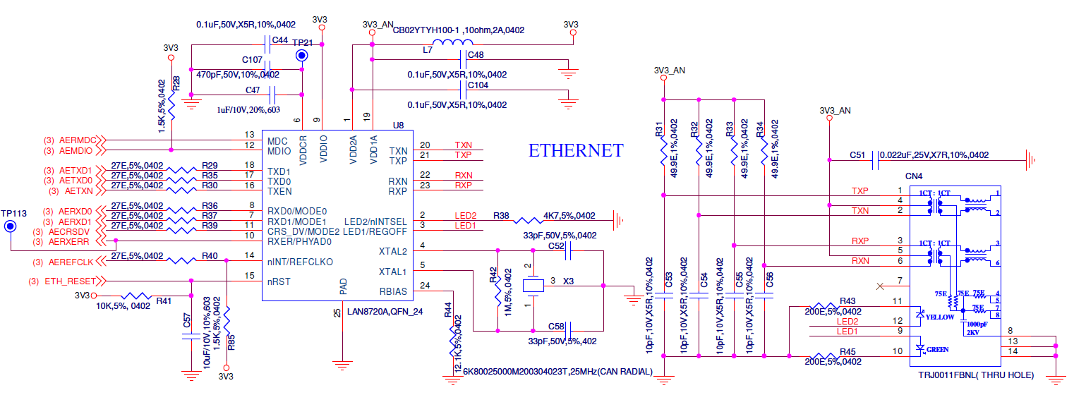
I am using STM32F207 microcontroller operating with 8 MHz crystal.

I am interfacing MAC in microcontroller to PHY (LAN8720A) through RMII.

LAN8720A PHY operating with 25 MHz crystal. It generates 50 MHz reference clock to microcontroller.

Even though CAT5 cables were not connected to RJ45 connector, PCB is generating the radiation emission.

How can I arrest this radiation?

We followed LAN8720 layout guidelines, but we faced radiation emission. Even though LAN8720A development board also generated radiation emission.

Please suggest how to route 50 MHz reference clock from PHY to microcontroller.

How do I arrest the radiation emission? My PCB is exactly the same as the LAN8720 development board.

You can see in the below link:

http://www.microchip.com/DevelopmentTools/ProductDetails.aspx?PartNO=evb8720

Observed points: When 25 MHz crystal pins are shorted with wire, there is no radiation.
enter image description here

enter image description here

enter image description here

\$\endgroup\$
3
  • 2
    \$\begingroup\$ Can you provide a screenshot of your PCB routing ? Because your schematic is not the same as the SMSC reference design, so you'll have some minor changes but they can be tricky. \$\endgroup\$
    – zeqL
    Commented Oct 11, 2014 at 22:52
  • 1
    \$\begingroup\$ I have basically the same problem, using a LAN8720A (RMII) and interfacing to a LPC4078. I have the additional (bulk) capacitance (10uF X7R 10V) and I have followed all the guidelines. My Next step is adding a ferrite on the VDDIO supply. Also I will try using an external 50MHz oscillator. Will get back with the result in a few days. \$\endgroup\$
    – Thor Bruun
    Commented Oct 28, 2014 at 14:41
  • \$\begingroup\$ Pin 14 REFCLK is the problem. Cut it temporarily and all the harmonics will dissapear. \$\endgroup\$
    – user58754
    Commented Nov 21, 2014 at 7:33

2 Answers 2

2
\$\begingroup\$

You're going to have to debug it.

First, how much over the emission limit are you?

Second, is there significant 25MHz noise on the supplies? If you're lucky you may simply have to decouple them better.

Third, which signals are radiating most? For example, if you lift TXP,TXN at the PHY, does the noise go away? (Alternatively if you have software means to disable bits of the PHY, that can save some knife/solder work)

Fourth, when you find the culprit you have to remedy it. For example, screening around the TXD/RXD traces, or ferrite chokes on them, or improve their terminations, or provide current return paths from termination to the PHY chip.

\$\endgroup\$
0
\$\begingroup\$

It seems like you need more decoupling. You need to put a large capacitor and a small capacitor as close to the chip as possible, with a smaller cap being more close. I would also recommend to put a separate inductor on the middle point of the trafos, where 3.3V power comes in. Does your inductor, after which 3.3V becomes 3.3V analog, have enough current capabilities? Finally, I've been in your shoes with a different application (not STM32) and my solution was to provide 25MHz clock signal out of the main controller... It simply ate too much power for 25MHz oscillator to work, so it radiated a lot...

\$\endgroup\$

Your Answer

By clicking “Post Your Answer”, you agree to our terms of service and acknowledge you have read our privacy policy.

Not the answer you're looking for? Browse other questions tagged or ask your own question.