2
\$\begingroup\$

I have a 3-state switch, It has 3 pins. It can have 3 state as you can see in the picture below. when it's off (i.e on O) the middle pin is not connected to anything! When it's on I, the middle pin is connected to I and when it's on II the middle pin is connected to II. Easy, Right?!
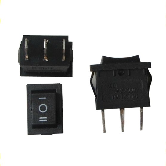
Rocker Switch 3-Pin

Now, I have two 5 volt DC fans and a 5 volt battery. I wanted to build a connection between these four elements that when the switch is on O, both fans are off. When it's on I, one fan is on and when it's on II, both fans will be on. I wanted to avoid using any other logical elements like gates or diodes, etc...
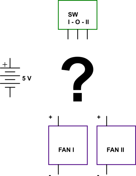
schematic

simulate this circuit – Schematic created using CircuitLab

All I want to have is just one switch, two DC fans and one DC battery. I couldn't figure it out how to do it, so I'm asking here! :)

If there is no way of doing it, is there a way to build it with minimum extra required elements?

\$\endgroup\$
6
  • 1
    \$\begingroup\$ Looks like single pole double throw, with ON - OFF - ON state. You cannot actually do what you want, with both on at once in a certain state. you CAN have "left" and "right" Fans on or off though. But only one at a time. \$\endgroup\$
    – KyranF
    Commented Oct 14, 2014 at 10:59
  • \$\begingroup\$ @KyranF, Thanks for your comment. so there is no way? :( what about adding some diodes to the circuit? \$\endgroup\$
    – Shamim
    Commented Oct 14, 2014 at 11:05
  • \$\begingroup\$ Oh, I misread it, i thought you needed Fan A on during I, Fan B on during II, and both fans on with the O state. You may just connect the + of Fan A to I, and the + of BOTH fans to II. You do not need a diode. It will just be the two fans in parallel from the same output. No diodes needed. \$\endgroup\$
    – KyranF
    Commented Oct 14, 2014 at 11:21
  • 1
    \$\begingroup\$ @KyranF, That's not right! when the + of both fans connect to II then the +s are connected! so when the switch is on I, both fans will be on!! \$\endgroup\$
    – Shamim
    Commented Oct 14, 2014 at 11:28
  • 1
    \$\begingroup\$ Alternatively buy the equivalent dual pole version of the switch. \$\endgroup\$
    – user16324
    Commented Oct 14, 2014 at 19:39

1 Answer 1

6
\$\begingroup\$

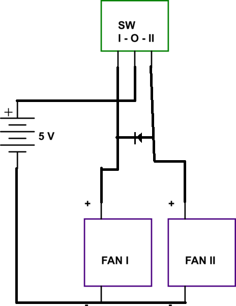
To do what you want, you will need at least one diode in the circuit, between poles I and II, At the expense of having a voltage drop in one of the fans.

enter image description here

When in position I, the diode will not let any current pass trough it, so only Fan I will spin. When the switch is in position II, Fan II will get power, and the diode will let current trough it (with some voltage drop) and fan I will also get power. Because of the voltage drop, Fan I will spin slight slowly than if it were directly connected to the power supply.

For small currents, any ordinary diode will do the job, like 1n4148 or the 1n400X series. Take a look at the datasheets of these models (and the fans, if available) to see the current specs.

\$\endgroup\$
5
  • \$\begingroup\$ what is wrong with just the + of both fans going to the II terminal? There is nothing wrong with having the fans in parallel. \$\endgroup\$
    – KyranF
    Commented Oct 14, 2014 at 11:22
  • 1
    \$\begingroup\$ If you have that, you will not be able to turn on one fan and let the other off, because you will always have a voltage across both. The current will flow in both fans, and they will spin. If you draw the circuit is easier to see. With the diode, when you put the switch in position I, there will be 5V at the cathode and 0V (because pole II is disconnected) in the anode. When you have this, the diode will be reverse polarized, and will not let the current pass trough its terminals. \$\endgroup\$ Commented Oct 14, 2014 at 11:29
  • 1
    \$\begingroup\$ ah yes, i see now. The first one turning on will indeed cause the second one to turn on, without the blocking diode. good work mate \$\endgroup\$
    – KyranF
    Commented Oct 14, 2014 at 11:34
  • \$\begingroup\$ @ricardomenzer Thanks for your answer. I think your solution is the closest thing i can get! I'll wait some and if didn't find any solution, then will mark yours as the correct answer. :) \$\endgroup\$
    – Shamim
    Commented Oct 14, 2014 at 11:43
  • 1
    \$\begingroup\$ to have the closest match in voltage (and therefore speed of the fans) you should try to use a Schottky diode with as low voltage drop as possible. If it's super annoying you can of course use two diodes, one going to each fan so they have the same drop. @Shamim \$\endgroup\$
    – KyranF
    Commented Oct 14, 2014 at 11:47

Your Answer

By clicking “Post Your Answer”, you agree to our terms of service and acknowledge you have read our privacy policy.

Not the answer you're looking for? Browse other questions tagged or ask your own question.