1
\$\begingroup\$

This is borderline electronics, but I think many more of us here have done this kind of studies.

I'm heating an aluminium plate with an Aluminium clad power resistor by mounting it on it and applying 25W of power, just like on the following schematic: enter image description here Note the thermal equivalent model I think it corresponds to, including the temperature nodes.
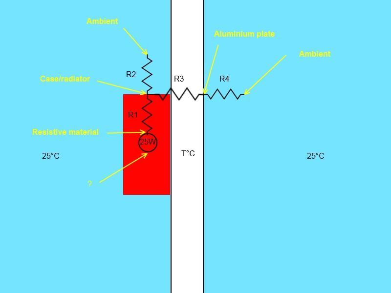
  1. What is the 0°C terminal of the power source connected to in that case? Ambient (as usual), or aluminium plate? How do we know?
  2. I can estimate R3 (0.5K/W) and I have a rough calculation of R4 (4.7K/W which I find really really odd*), but on the datasheet of the resistor I'm using I don't know if the thermal impedance is R1+R2 (junction to ambient) or R1 (junction to case). Numbers seem to point to R1+R2, but how do I know R1 then?

Goal: Calculate the temperature T of the aluminium plate at equilibrium.

*: Addendum: I've used the 0.225m².K/W value of this link together with the surface of my plate to find that, which means a 360x131 mm² plate radiates less than the resistor heatsink?

\$\endgroup\$
2
  • \$\begingroup\$ Convection is notoriously hard to guesstimate. I've used the number from here, thermopedia.com/content/660 5W/(K*m^2) (close enough to your number.) One thing weird about your link is that the thermal transmittance is not one over the thermal resistance. \$\endgroup\$ Commented Oct 17, 2014 at 17:37
  • \$\begingroup\$ You're right, it's a convection coefficient. But if you find the same value it suits me. What do you think about the other questions? \$\endgroup\$ Commented Oct 18, 2014 at 13:22

1 Answer 1

1
\$\begingroup\$

I'll try an answer.
I'm confused by your first question but let me try this,

So in doing this type of modeling there is the following analogy.

  • Temperature (T) = Voltage
  • Heat (power) (W) = Current
  • Heat capacity (J/K) = Capacitance (coulumbs/volt)
  • Thermal resistance (K/W) = resistance (V/A)

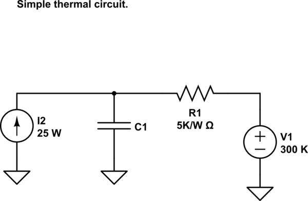
schematic

simulate this circuit – Schematic created using CircuitLab

So I usually make my temperature reference 0 K. (You could make it 0 C, but it gets confusing if you ever want to work at temperatures below zero C.) The temperature reference like a voltage reference is somewhat arbitrary.

So then my circuit does this. There is a 25W Heater (current source) feeding your Al plate. (I'm ignoring the thermal resistance in the source.. more below.) This goes into the Heat capacity of your plate. (if you tell me the volume of your plate then the heat capacity is about 3 J/K per cm^3.) This plate is connected to the outside world through a resistor to 300K. So you can now go ahead and solve this. And find out not only the final temperature of the plate, but also the time constant.. how long does it take to get there.

OK now the resistance of the heating element. You could add this in as a resistor between the current source and plate C. You only care about this if you want to know how hot the resistor inside will get. I assume the number in your link is to the case. I'd further ignore the convection loss of the heater body, (assuming it's small in area compared to the plate.)

Once I make this type of model I'll get a little thermo-couple and measure temperatures here and there and see how good the model is. (It looks like your plate will get hot.)

\$\endgroup\$
5
  • \$\begingroup\$ You clarified everything, thanks. I wasn't sure what the other terminal of the power source was connected to, but now it's cristal clear that it has to be a 0° and as you said more convenient on the Kelvin scale. \$\endgroup\$ Commented Oct 18, 2014 at 23:32
  • \$\begingroup\$ One note though, if the resistor is also dissipating through its own heat sink to ambient, doesn't it actually matter for the temperature of the plate as the resistors conductances will add in parallel (you wrote "you only care about this if you want to know how hot the resistor inside will get") \$\endgroup\$ Commented Oct 19, 2014 at 17:42
  • \$\begingroup\$ @MisterMystère, Re: resistor heat sink. Yeah the resistor body will be hotter than the plate and so will loose a bit more due to convection. But it's all a matter of the area (and air flow) I assume your Al plate is much bigger than the resistor body. And hey, you could always add that part in to the above simple model. \$\endgroup\$ Commented Oct 20, 2014 at 12:52
  • \$\begingroup\$ Yes. I'm really surprised that this resistor is rated 50W if the convection resistance is higher than the Al plate one's (5K/W), but that's also logical that -being much smaller- that resistance is indeed higher. After all that resistor should be safe without mounting it anywhere. Confusing. \$\endgroup\$ Commented Oct 20, 2014 at 13:26
  • \$\begingroup\$ @MisterMystère, Grin. Well no it's not good to it's rated power without proper mounting. (At least that is my expectation for any part that come with mounting holes :^) \$\endgroup\$ Commented Oct 20, 2014 at 13:43

Your Answer

By clicking “Post Your Answer”, you agree to our terms of service and acknowledge you have read our privacy policy.

Not the answer you're looking for? Browse other questions tagged or ask your own question.