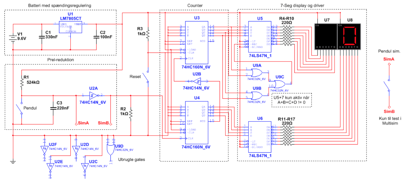
I just started studying electrical engineering this semester, and I'm currently working on following impulse counter:

The circuit is basically a power supply regulated to 5V, a pendulum acting as a switch connected to the clock of a counter, with a bit of noise-reducing circuit to limit the impulses, and some 7-seg displays with drivers to display the value of the counters.
I have a few issues with the circuit, that I would love to get help or inspiration on how to solve:
- The counter (U4) always starts at 1 instead of 0, so I have to use the implemented reset button every time I power on the circuit. Not a major issue, but it would be awesome to find a way to solve this. I assume it is because of the small delay whilst the capacitor (C3) is "loading" initially - making the inverted output HIGH, then LOW when powering on the circuit. If that is the case, I don't know how to solve it while retaining the noise-reducing circuit.
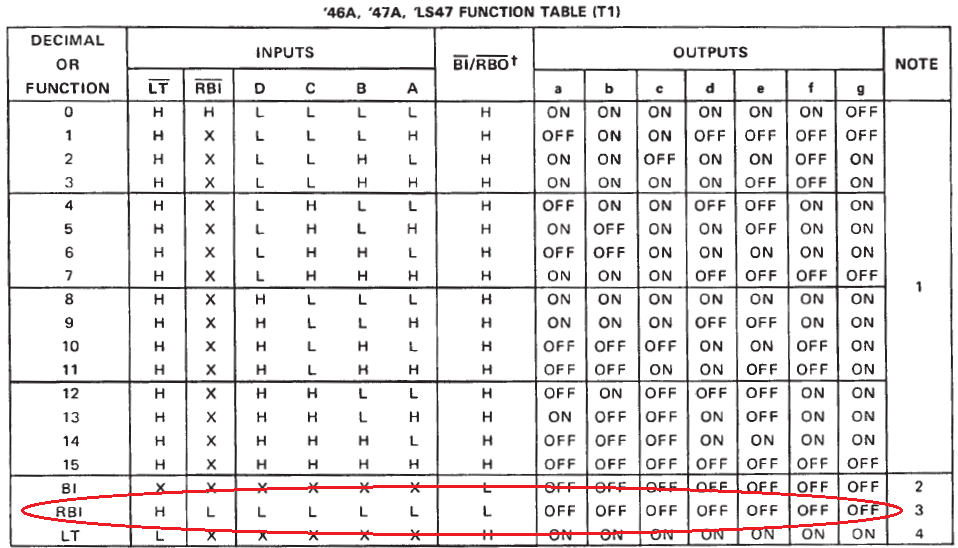
- I implemented some logic to keep 7-seg 2 (U7) turned off initially (when it should be displaying 0) and turns on only for 1-9. This works as intended when simulating the circuit in MultiSim, but when I realise the circuit on a breadboard it acts a bit unexpected. Initially it works as intended, but after 7-seg 2 (U7) has been turned on once, it never turns off again and instead displays the value '0' when reset.
I appreciate any help on solving the issues!
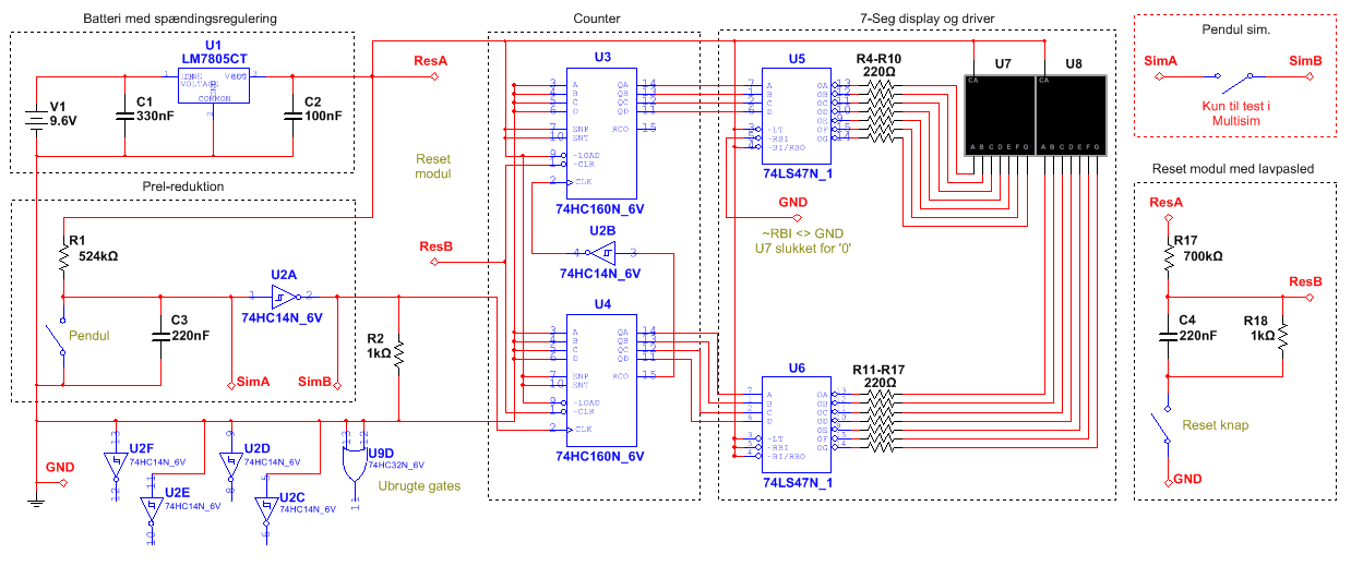
EDIT: Solution for the problem, by attempting to implement suggestions by Dan:
 Added another (slightly slower) low-pass filter connected to the counters ~CLR-pin to reset the counter to 0 initially, and replaced the logic for U5's RBI-pin with a ground connection to solve the display issues.
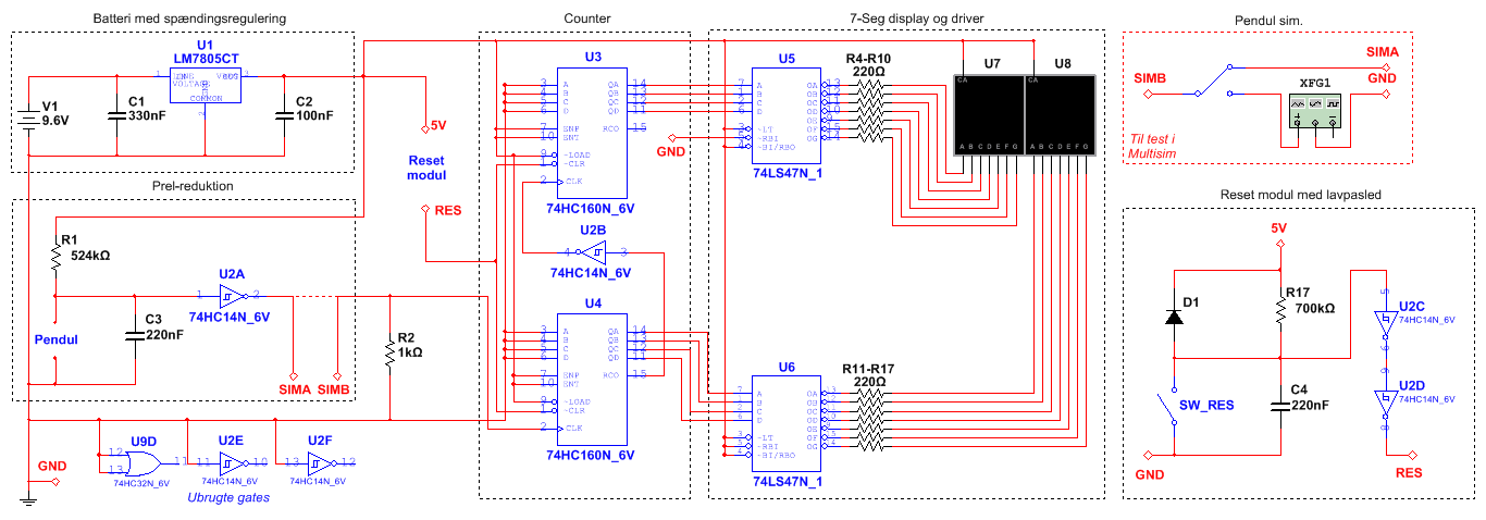
EDIT2: Final working solution if anyone is interested, thanks to suggestions:
 Fixed the reset switch and improved the reset module with a diode and some amplification to make it more reliable. Works great now!

