0
\$\begingroup\$

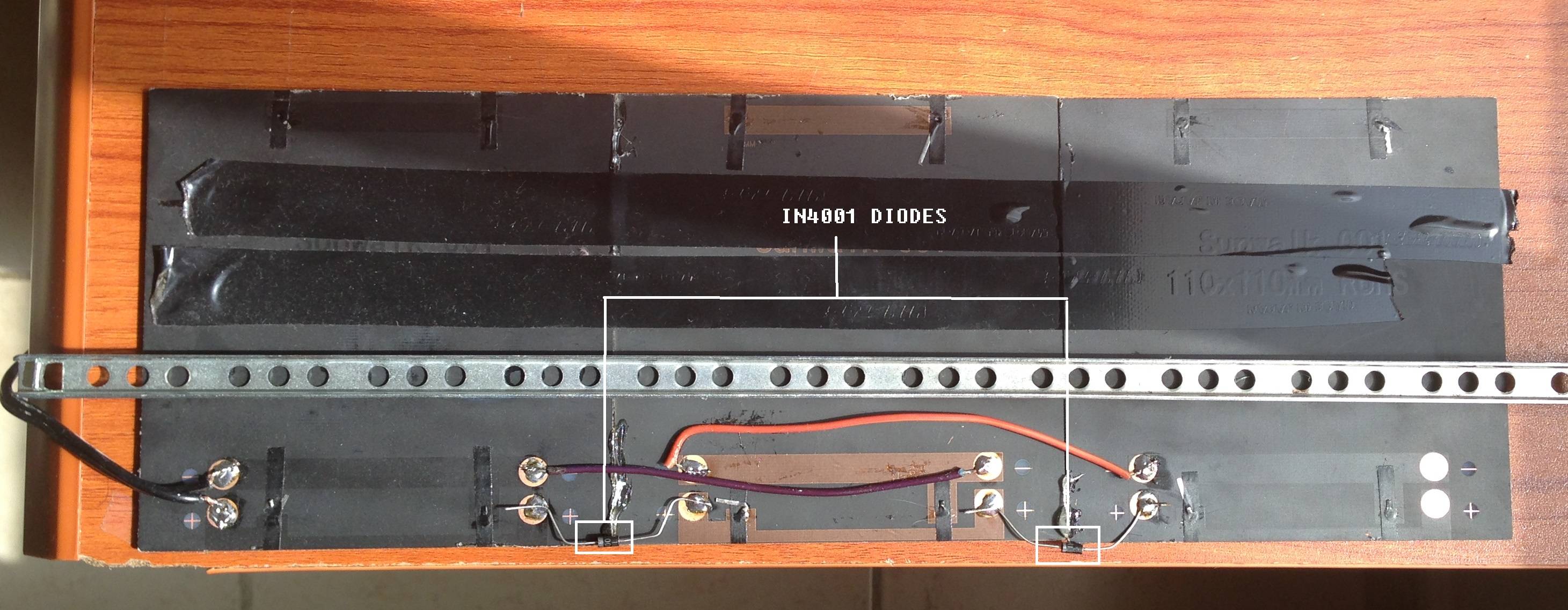
Solar Panel Full View

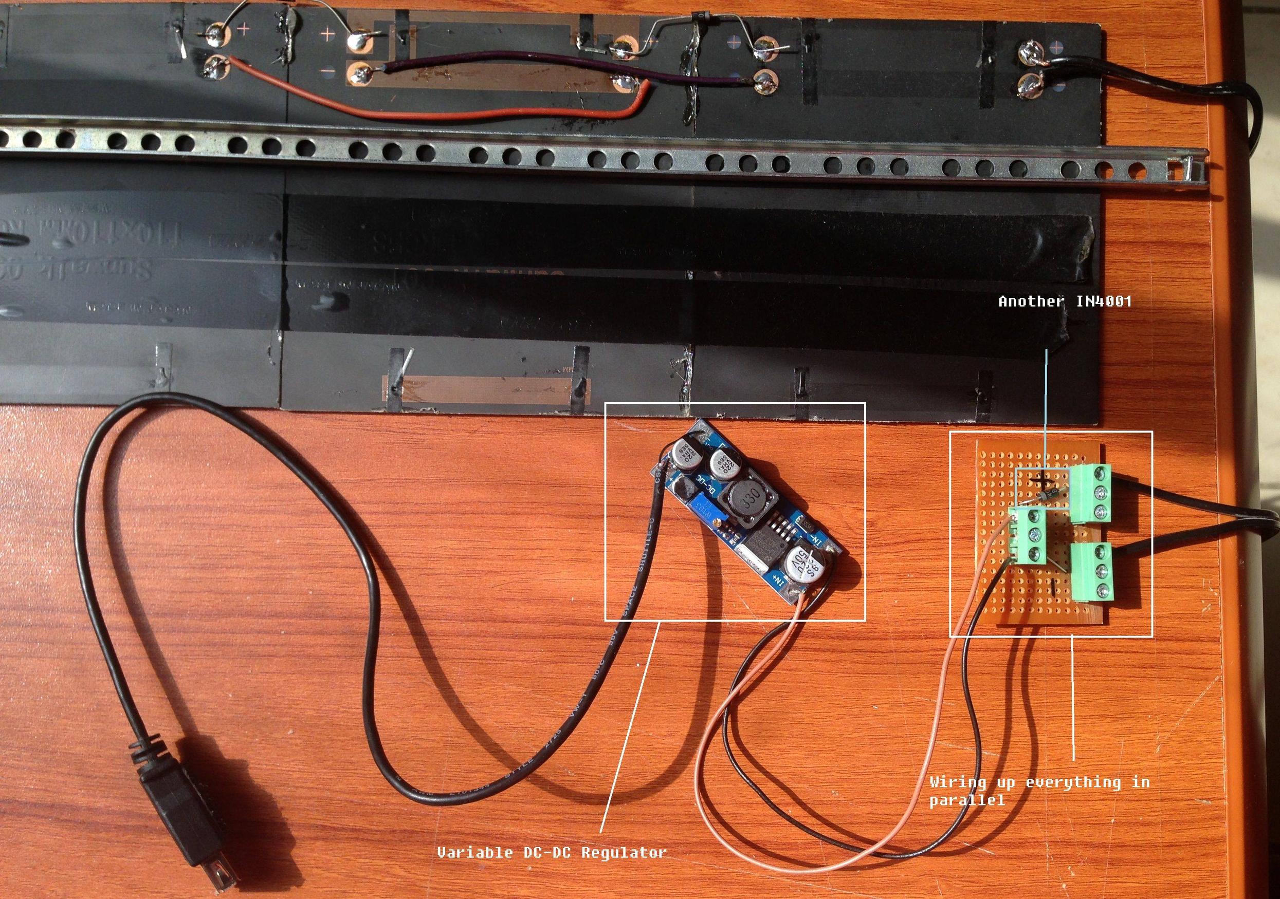
The Entire Thing

The Materials :

1) 3 X 1.5W 6V Monocrystalline panels @ 320mA

2) DC-DC Variable Voltage regulator

3) 3 X 1N4001 Diodes

The Problem : -

I have connected the panels (which give about 203 mA realistically) in parallel wiring with an 1N4001 diode at each of the positive terminals to prevent reverse flow of current. The entire array generates around 7.09 V at 610 - 720 ma in ideal conditions. Now using my multimeter, when I measure the current (used the positive and negative leads of the multimeter ----> 10 A unfused) at the breakout board it displays 0.61 A which is enough to charge any sort of USB Devices since the typical USB 2.0 current output ranges from 250 mA to 500 mA. On measuring the current from the ends of the voltage regulator (5V output) it displays 0.98 A. It charges devices with no charge protection and doesn't charge the ones with charge protection.

At this point I'm really confused. Is there a problem with the wiring, a problem with how I measured current or is the current too low? because according to my calculations there should be plenty of power for charging phones. Please help me out here.

Thanks in advance :)

\$\endgroup\$
1
  • \$\begingroup\$ When you are measuring the current, is that short circuit or through a burden resistor? \$\endgroup\$
    – pjc50
    Commented Dec 8, 2014 at 17:29

2 Answers 2

1
\$\begingroup\$

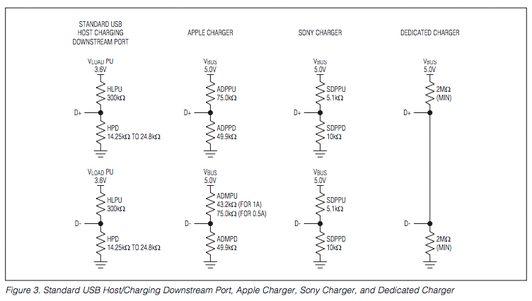
I'm guessing you don't have the required resistor dividers on the D+ and D- lines to tell the phone / device that it can draw more than 100mA safely.

enter image description here

\$\endgroup\$
2
  • \$\begingroup\$ I didn't quite understand why the standard USB host charger has 3.6 V output and the others have 5. Also, Do i have to wire two resistors to each of the D+ and D- lines ? If so where would the ground of D+ and D- be attached to ? \$\endgroup\$
    – Devnath
    Commented Nov 13, 2014 at 12:28
  • \$\begingroup\$ It's all about getting specific voltages onto the D+ and D- lines. You can use any voltage for the upper side of the voltage dividers, as long as you end up with the right voltage. The simplest is the dedicated charger since it just needs 2 resistors. Ground goes to ground. There is only ground. What's the confusion there? \$\endgroup\$
    – Majenko
    Commented Nov 13, 2014 at 12:57
0
\$\begingroup\$

I think the problem is that you have too MUCH current instead of not enough. The typical is 250mA - 500mA; that is the TARGET. More is not merrier in these situations: no one wants to charge their phone with so much current it may overload it. You also need to know how much current your device draws. Normally if the device wants, 100mA @ 5V, don't give it 500mA because it will burnout the battery. That is why the charge protection circuitry is trying to negate the charge input coming in because it is nearly double the charge typical. Always stay within the stated typical if possible, it may save your project.

\$\endgroup\$

Your Answer

By clicking “Post Your Answer”, you agree to our terms of service and acknowledge you have read our privacy policy.

Not the answer you're looking for? Browse other questions tagged or ask your own question.