2
\$\begingroup\$

I am building a simple bi-polar power supply, that will be capable of -/+12VDC at around 1.25A. I have a mains transformer that brings 230VAC down to ~20VAC, with single windings on both sides. And I was wondering, if its possible to generate a +/- voltage from a a single winding on the secondary side, so without the center tap. If it is, what is the best/ most efficent or most used way of doing it?

I would really appreciate if you could provide a schematic.

Best regards!

EDIT:

Would it be better if I used a full-wave rectifier getting only a positive voltage and then using a buck/boost or a similar method to invert it to a negative voltage?

What is the advantage/disadvantage of both approaches?

\$\endgroup\$
2
  • \$\begingroup\$ Honestly the simplest solution is to get another transformer like the one you have already OR to get a different one that has either a center tapped secondary or two separate secondaries. \$\endgroup\$ Commented Nov 8, 2014 at 20:23
  • 1
    \$\begingroup\$ I know, but I already have this one at hand. And transformers here arent really that cheap. \$\endgroup\$
    – Golaž
    Commented Nov 9, 2014 at 10:19

2 Answers 2

3
\$\begingroup\$

You can create a bi-polar supply from a transformer without a center tap as long as you can live with just half wave rectification for the positive and negative supply rails.

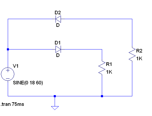
Here is a schematic that shows it is feasible. Note that I left out the filter caps so that you can see the half wave rectified waveforms.

enter image description here

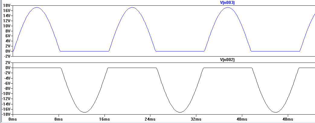
Here are the waveforms of the two output voltages:

enter image description here

Half wave rectification places some requirements that you add bigger capacitors to the output to smooth the DC voltage to less ripple than would be needed if you did full wave rectification. It can also be beneficial in this case to use a higher transformer secondary voltage so that more ripple on the capacitors would not cause your down wind voltage regulator to drop out cycle by cycle.

Note that it is conventional to do full wave bridge rectification on an untapped transformer secondary. Unfortunately you cannot get two bridge rectifiers to work on a single untapped transformer secondary to get a bipolar output.

\$\endgroup\$
1
  • \$\begingroup\$ Please see edit in my question. \$\endgroup\$
    – Golaž
    Commented Nov 8, 2014 at 20:01
1
\$\begingroup\$

There is no disadvantage to using two half-wave rectifiers for plus and minus supplies other than your filter capacitors having to be double the capacitance if your loads on the +/- rails are reasonably balanced (or, equivalently, most of the load current flows from the + rail to the -).

If (as frequently occurs) most of the load is on the + rail and you need a relatively small current on the - rail then you should consider an inverting switching regulator of charge pump. The issue is inefficient use of the transformer core- you'll only be able to use a fraction of the watts the transformer is capable of, but balance doesn't really improve the max current much. If the spec was 1.25A on the plus rail and 100mA on the minus rail you could use a transformer that was almost half the weight with full wave rectification, but with half wave the capability on the minus rail goes unused.

According to this app note, you'd need about a 5A transformer to get +/-1.25A or less regardless of balance.

Also note that regardless of the transformer configuration you choose, with linear regulators and a 20VAC transformer you'll be burning around 40W in wasted power at +/-1.25A, which is a lot of heat to get rid of reliably and a lot of wasted electrical energy.

\$\endgroup\$

Your Answer

By clicking “Post Your Answer”, you agree to our terms of service and acknowledge you have read our privacy policy.

Not the answer you're looking for? Browse other questions tagged or ask your own question.