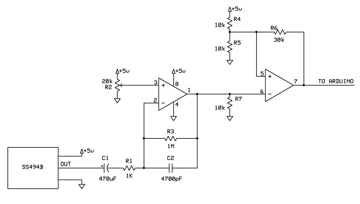
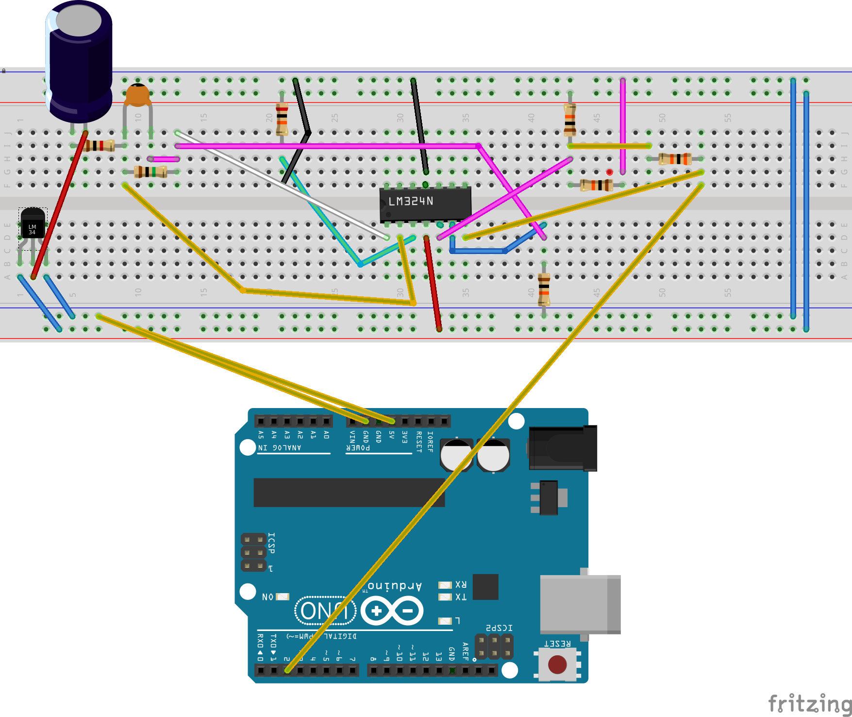
If that image is accurate, then I would suggest simplifying your board layout. When I was a TA for Electronics lab classes I often saw students get confused by a maze of criss-crossed wires on the board. Starting with the IC is definitely a good idea. Some of your resistors can connect directly from the LM324 pin to +5V or ground. R7 is a prime example, and either R4 or R5 could be moved as well. Pins 1 and 6 can be connected together with a short wire right next to the IC.
Also, try to move your components closer to the relevant IC pins. The top left of your board with C1/R1/C2/R3 is compact and easy to follow, but it's off in a corner, and there's no reason for the SS494B to be on the other side. If you wanted to add another circuit, you'd barely have any room! You can also move your IC so that the gap in the power-ground rows isn't right next to pins that need them. Maybe put pins 1 and 14 next to gaps. The power and ground wires can be shorter. If you connect the power and ground rows to the nearest holes possible, it leaves more room for signal wires to go between the pins.
Each of these things is a small change, but if you do them all you'll suddenly find that you have half as many wires and that most of your connections are straight lines. It's much easier to work with.


