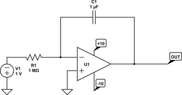
Take the integrator. Suppose you apply a voltage to the resistor, and the capacitor starts off with 0V across it.

simulate this circuit – Schematic created using CircuitLab
The voltage at the output will rise from 0V towards +10V at +1 volt/second, so after 10 seconds the output voltage will (ideally) reach the power supply voltage. At that point the op-amp will saturate or "rail" at the (ideally) positive supply voltage.
The op-amp can no longer operate in its active region so the output looks like its shorted to the +10V supply. At the moment of saturation, the voltage on the inverting input is 0V, but after that it looks like a classic RC circuit and you'll see the kind of RC response you'd expect on the inverting input (while the non-inverting input obviously will remain at 0V since it is grounded).
After a very long time the voltage at the inverting input will thus be V1. Since it's driving the op-amp output towards the positive rail (negative input on the inverting input wrt the positive input) the op-amp stays saturated at the positive rail.
You can do a similar analysis for a positive input to the integrator and similar inputs to the differentiator that cause the op-amp output to saturate.

