3
\$\begingroup\$

I am trying to find the voltage at NODE1. My initial approach was to find the current starting from the \$15\$V source then going through \$R_1\$ and \$R_3\$ to ground. Then calculating the current from \$14\$V source through \$R_2\$ and \$R_3\$ to ground. Then adding the two currents and using Ohm's law with total current and \$R_3\$ to find voltage from NODE1 to ground. This seems plausible to me only because of KCL (total current entering a node must equal current exiting node). However my answer is incorrect as I have proved both in SPICE and on breadboard.

What am I missing? I would appreciate any suggestions that don't totally give me the answer.
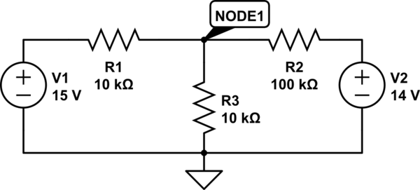
schematic

simulate this circuit – Schematic created using CircuitLab

\$\endgroup\$
3
  • 2
    \$\begingroup\$ Why not use superposition? Then you've just got a pair of voltage dividers. \$\endgroup\$
    – Null
    Commented Nov 26, 2014 at 2:27
  • \$\begingroup\$ That did it. Can I assume then, for example, the 14V source "sees" the 15V source as a short? And thus the 14V source "sees" a total resistance of 105k? \$\endgroup\$
    – disorder
    Commented Nov 26, 2014 at 3:12
  • \$\begingroup\$ Exactly. And the resistances will give you the voltage from the voltage divider equation. Then do the same for the 15V source, and add up the two contributions. \$\endgroup\$
    – Null
    Commented Nov 26, 2014 at 3:18

2 Answers 2

5
\$\begingroup\$

The easiest way to do this is to use superposition. Set one source to \$0\$ (i.e. shorted) and find the node voltage due to the other source, then set the other source to \$0\$ and find the node voltage due to the first source. Add the two contributions for the node voltage due to both sources.

For the case with the \$14\$V source set to \$0\$ (finding the contribution of the \$15\$V source) the circuit looks like this:

schematic

simulate this circuit – Schematic created using CircuitLab
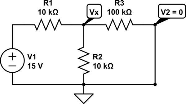
\$R_2\$ and \$R_3\$ are in parallel since \$V_2\$ is shorted, and \$V_x\$ can be found using a simple voltage divider:

$$V_x = \frac{R_2||R_3}{R_2||R_3 + R_1}15\text{V}$$

It's a similar process for finding \$V_y\$, the contribution of the \$14\$V source to the node voltage (with the \$15\$V source set to \$0\$).

Then by superposition $$V_{\text{NODE}1} = V_x + V_y$$

\$\endgroup\$
4
\$\begingroup\$

Here is a very useful trick you can use for n resistors connected to n voltage sources:

schematic

simulate this circuit – Schematic created using CircuitLab
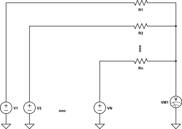
$$V_\mathrm{M1} = \left (\frac{V_1}{R_1} + \frac{V_2}{R_2} + \cdots + \frac{V_n}{R_n} \right ) \times (R_1 || R_2 || \cdots || R_n)$$

Where $$R_1 || R_2 || \cdots || R_n = \frac{1}{\frac{1}{R_1} + \frac{1}{R_2} + \cdots + \frac{1}{R_n} }$$

So, it can also be written:

$$V_\mathrm{M1} = \frac{\frac{V_1}{R_1} + \frac{V_2}{R_2} + \cdots + \frac{V_n}{R_n} } {\frac{1}{R_1} + \frac{1}{R_2} + \cdots + \frac{1}{R_n} }$$

In your case:

  • R1 = 10K, V1 = +15V
  • R2 = 10K, V2 = 0V
  • R3 = 100K, V3 = +14V

$$R_1 || R_2 || R_3 = \frac{100}{21}\ \mathrm{kΩ} $$

and I'll leave the rest for you...

\$\endgroup\$

Your Answer

By clicking “Post Your Answer”, you agree to our terms of service and acknowledge you have read our privacy policy.

Not the answer you're looking for? Browse other questions tagged or ask your own question.