0
\$\begingroup\$

Hello I am creating a little device, which has a total number of 30 tactile switches arranged in a matrix with 3 rows and 10 columns. My problem is, that I have only left 5 IO pins on my AVR micro-controller. For normal, I would scan my switch matrix, with enabling only one of the 10 columns at a time, and than read the input from the three rows. This is, how I determine the pressed switch, but this would need 13 IO pins.

My first approach, to find a solution was using a ring counter, but I was a little bit confused, on what it actually does, and how it works. I could also find only so called Johnson counters in my preferred electronics store. Can anyone help me out with this?

EDIT: Sorry I forgot to mention, that I also need to detect, if multiple keys are pressed. I am using diodes on each switch to prevent shorting(hope I can call it like this, not so experienced in english).

\$\endgroup\$

2 Answers 2

1
\$\begingroup\$

I'm going to suggest that you learn about shift registers. 4 pcs of a 8-bit parallel-to-serial shift register would work very well for you and would need a maximum of 3 lines to your controller. Some of those lines can even be shared with other functions if you are clever.

The CD4021 is a nice part that I use in many of my designs. You will need a pull-up resistor for each input. I use SIP bussed resistor networks - 10 pin package gives you 9 pullup resistors in a very small space.

You can also mount the shift registers very close to your switches to minimize the number of wires to the controller.

\$\endgroup\$
0
\$\begingroup\$

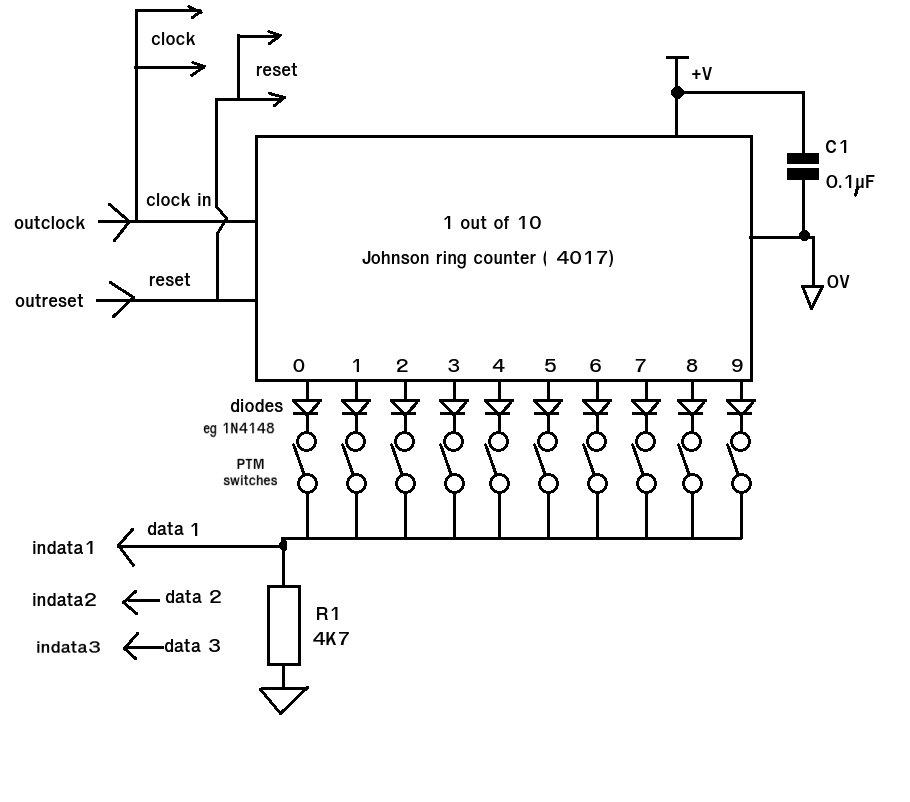
As you have the luxury of 5 I/O pins here's a suggestion based upon the 4017 (one out of 10) Johnson ring counter. The full circuit would use three 4017 ICs with the CLOCK and RESET lines in common and separate DATA lines for each chip (data1,data2,data3) which would be read in parallel.

This allows for all 30 switches to be read in 10 read cycles and also allows for multiple switch operations. The diodes used are general purpose types such as a 1N4148. Their function is to prevent a LOW output from being connected to a HIGH output and shorting it out (pulling it LOW). R1 is a pull down resistor. The value is not critical so anything between a few hundred ohms and a few 10Ks would be fine. Only ONE output is HIGH at any time and this output is the only one that can produce a HIGH on the data line (input to controller) IF the switch is closed.

Basic circuit. (1 out of 10)
enter image description here

This shows the set up for a single 10 switch read. The data (input) line will be held LOW by R1 (value not critical). To scan the switches the counter is first reset so output 0 goes HIGH. If switch '0' is pressed then it will place a voltage across R1 and the data line goes HIGH if the switch is not pressed the data line will be LOW. This can be read by the controller. The controller then produces a clock pulse and output 1 goes HIGH. If switch 1 is closed the data line will be HIGH. If the switch is open the data line will be LOW and so on. By clocking through all the outputs each switch can be tested making it possible to 'see' multiple key presses by storing each value in turn.

Meta Code.

Clockcount == 0; // a counter to identify which 4017 output (bit position)
lastpress == thispress ; // remember last keypress pattern (16 bit) - useful for monitoring changes and debouncing etc.
thispress == 0; set up new keypress variable (bit pattern of switches)
Toggle(Resetpin); // reset 4017 for '0' output HIGH
inputupdate(datapin); // get the value of the data line (HIGH = keypress, LOW = no keypress)

// and store new value in thispress (16 bit switch image)
Loop until Clockcount = 10 ; {
  Clockcount++ // increment clock counter (1,2,3,4,5,6,7,8,9)
  Toggle(clockpin); // increment 4017 counter for next output 
  inputupdate(datapin); // get the value of the data line (HIGH = keypress, LOW = no keypress)

  // and store new value in thispress
}
\$\endgroup\$
5
  • \$\begingroup\$ Thanks for the help. Mostly your circuit equals my version, except, I had no clue, how to drag the columns up to 5V! \$\endgroup\$
    – ruabmbua
    Commented Nov 30, 2014 at 16:11
  • \$\begingroup\$ Now I have to find the 4017. I am not so experienced in electronics(I come from the programming section), is there any way, to find these integrated circuits fast? My preferred shop(farnell.at) does not ship the 4017. How can I find another one, which meets my requirements? \$\endgroup\$
    – ruabmbua
    Commented Nov 30, 2014 at 16:15
  • \$\begingroup\$ Will this one do the job? Notice, that it provides 10 output pins, which would be perfect.at.farnell.com/on-semiconductor/mc14017bcpg/… \$\endgroup\$
    – ruabmbua
    Commented Nov 30, 2014 at 16:22
  • \$\begingroup\$ Do a search for 'decade counter' in the Farnell search and click on the DIP package and you'll see the 4017 versions. For a typical 4017 circuit set up/ pinout look at doctronics.co.uk/4017.htm \$\endgroup\$ Commented Nov 30, 2014 at 19:24
  • \$\begingroup\$ Thanks I already found one. I think I am getting into searching these parts. \$\endgroup\$
    – ruabmbua
    Commented Dec 3, 2014 at 8:10

Your Answer

By clicking “Post Your Answer”, you agree to our terms of service and acknowledge you have read our privacy policy.

Not the answer you're looking for? Browse other questions tagged or ask your own question.