I'm going to buy a holding electromagnet and a strike plate to hold some things, and I want to design my circuit (arduino-controlled) not to fry like bacon. I'm aware that since a holding magnet is an inductor, I should use a flyback diode and possibly a capacitor to handle the back EMF for when current is interrupted. However, what happens if the holding magnet is physically forced away from the strike plate? Work is being done to overcome the magnetic force, so I figure the energy goes somewhere, but how does that momentary change manifest in the circuit? Do I see increased current through the coil? Decreased current? And for that matter, what happens in the circuit when the magnet meets and locks to the strike plate?
Basically, I'm trying to determine if I need to handle a forward EMF spike as well as a back EMF spike, and my research hasn't taught me enough about magnetic fields to figure it out on my own.
EDIT
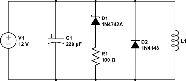
I'm currently using this circuit:

simulate this circuit – Schematic created using CircuitLab
L1 is the magnet; I don't know its inductance, but it has a series resistance of 20 Ohms. D1 is the zener that protects against overvoltage; R1 is there because the only zener I had was exactly 12V and I wanted some safety margin to avoid a short in case the power supply went high for some reason other than L1. D2 is the flyback; it protects against voltages less than -1V, which hopefully aren't enough to ruin the cap (a schottky would be better, but I don't have one lying around).
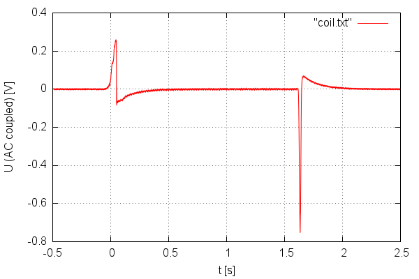
I operate this by turning the power supply on and off. In the future I'll put a Darlington between C1 and V1. It SEEMS to work and not damage anything even when I force the plates apart, so that's good, hopefully I'm not doing anything nasty to the power supply. I still need to look at this with a scope to make sure.
I did have the idea of putting my own inductor in series with L1. This would act to limit current changes caused by L1's inductance changing. Not sure if I'll do that.

