Just one small clarification before we go any further. MOSFETs, by themselves, cannot boost voltage. However, a higher voltage can be switched on and off through a MOSFET with a lower voltage. For example, your 9V source can be switched with a 5V signal from your Arduino. I suspect that's what you mean by "boosting voltage" using a MOSFET.
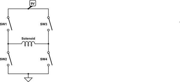
It looks very much like you want to construct a classical H-bridge topology. H-bridges allow you to control the direction of current through a load. In your case, the coil of a solenoid. An H-bridge is very simple if you think of the transistors as just four on/off switches that are independently controlled:

simulate this circuit – Schematic created using CircuitLab
When all four switches are open, no current flows and nothing happens. If, say, SW1 and SW4 are simultaneously closed, current will flow from the 9V source, though SW1, through the solenoid (from left to right), through SW4, and into ground. If SW2 and SW3 are simultaneously closed, a similar thing will happen, except the current will flow through the solenoid from right to left. Thus you have polarity control.
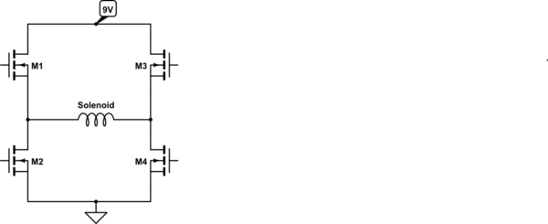
Now, let's replace these ambiguous switches with actual MOSFETs. We'll use all N-channel MOSFETs for now:

simulate this circuit
Imagine the gate of each MOSFET controlled by a separate digital line. Most likely GPIOs from your Arduino. Now it's just a matter of writing the code to activate the appropriate pair of transistors at the right time. It would be great if it was really that simple. But, unfortunately, it's not. There's one big gotcha when using transistors this way.
MOSFETs require a certain minimum voltage on the gate in order to activate. That minimum voltage, known as \$V_{gs(th)}\$, is relative to the MOSFET's source pin, not ground. In practice, you'll want a voltage a bit higher than the minimum. But I won't get into that here. The source pins of the low-side MOSFETs (M2 and M4) are grounded, so your Arduino's GPIO outputs will work. But the high-side MOSFETs (M1 and M3) have floating source pins. The direct voltage from an Arduino GPIO pin is not sufficient to activate the MOSFET.
From here, you have two options:
1) Use N-channel FETs for both high-side and low-side as shown in the schematic above. This is the more common method, as N-channel FETs have lower \$R_{ds(on)}\$ than P-channel. However, you will need to implement a bootstrap converter to activate the high-side FETs in order to overcome the problem described in the paragraph above.
2) Use P-channel FETs for the high-side and N-channel FETs for the low-side. Modern manufacturing processes have made P-channel FETs that are near in performance to N-channel. If the current load through the solenoid is not too high, this may be a simpler option as no bootstrap converter is necessary. However, you still can't drive the gates of the P-channel FETs directly from the GPIOs of the Arduino. A small, intermediary N-channel is typically used instead.
There are lots more things to work out before you'll have a functional H-bridge, but hopefully this will get you started. As you hone in on a specific circuit design, feel free to come back with more specific questions.


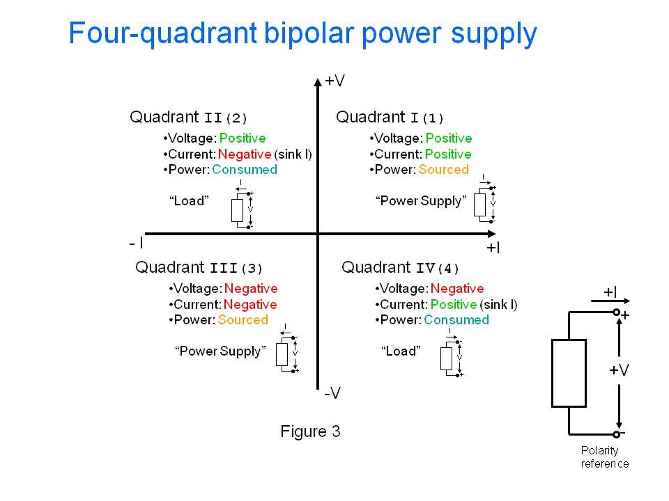
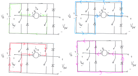
 And here is what the H bridge does for each quadrant:
