1
\$\begingroup\$

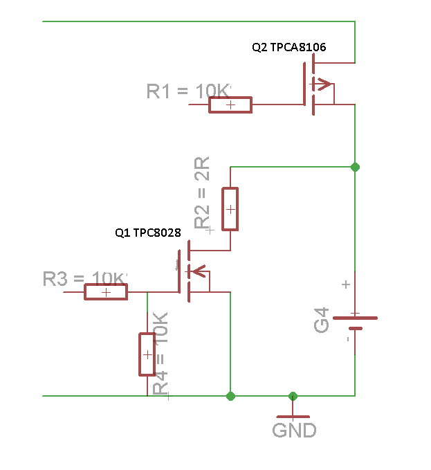
enter image description hereI need an Arduino based lithium battery tester that uses N channel Mosfets to switch On charging from and external power source and discharging through a 2 Ohm resistor. I have no issues with either charging or discharging circuit schematic, however i can not combine them together. I'm attaching the schematic for discharging the battery into the 2 Ohm resistor, please help with adding the components for making it able to charge the battery from an external, let's say 4.2V power source, all controlled by Arduino.

I also need to have a state when i'm Not charging or discharging so i guess for that purpose i need to use Pin 11 on Arduino

\$\endgroup\$
3
  • \$\begingroup\$ changed to an answer \$\endgroup\$
    – KyranF
    Commented Dec 21, 2014 at 11:17
  • \$\begingroup\$ I find your question and the follow-up a bit confusing. But I think your PFET, Q2, is backwards. When Q2 is off, that is supposed to disconnect the battery from a charger (not shown) connected to the high wire in your schematic, right? But it wont work because the body diode of Q2 will be forward biased. Connect the drain of Q2 to the battery and connect the source of Q2 to the regulated charger. \$\endgroup\$
    – user57037
    Commented Dec 21, 2014 at 17:10
  • \$\begingroup\$ yes @mkeith he got the PFET backwards. \$\endgroup\$
    – KyranF
    Commented Dec 21, 2014 at 21:17

1 Answer 1

1
\$\begingroup\$

Surely a high side PFET connecting the battery + terminal to the 4.2V external supply is enough. I hope you aren't doing anything unsafe, I really hope you've read about thermal issues, charge currents and voltage cycles with Lipo batties.

If you have the default logic state as the 4.2V thing connected to the battery, then have the system with a pull down resistor on Pin 12. Then when Pin 12 goes high, it will turn on the NFET low-side switch to provide the 2 Ohm load, and the gate voltage of the P fet will rise and turn it off, thus allowing you to test the battery without the 4.2V thing interfering.

You can swap the logic (not recommended, unless you also detach the battery when not in use) by putting a pull-up resistor on Pin 12 and driving it low to allow the battery to charge again.

\$\endgroup\$
10
  • \$\begingroup\$ I'm a bit confused, i tried before adding the P-fet, though it was getting hot and never went off. Could you please upload schematic. I have P channel TPCA8106 fet and N Channel TPC8028 fets. Also what should be the value for the pull-down resistor? I'm also uploading an updated schematic. Is it possible to attain the same goal with N channel fets only? cos i have many of those... thank you \$\endgroup\$
    – Adrian
    Commented Dec 21, 2014 at 13:30
  • \$\begingroup\$ I also need to have a state when i'm Not charging or discharging so i guess for that purpose i need to use Pin 11 on Arduino. Am i right? \$\endgroup\$
    – Adrian
    Commented Dec 21, 2014 at 13:55
  • \$\begingroup\$ See my comment above. I think your PFET was backwards. That is why it never turned off. \$\endgroup\$
    – user57037
    Commented Dec 21, 2014 at 17:11
  • \$\begingroup\$ It does now. Thank you. Do i need to connect a pull up or pull down resistor for the P channel fet also? \$\endgroup\$
    – Adrian
    Commented Dec 21, 2014 at 20:23
  • \$\begingroup\$ in theory a pull-up will turn it off, but that turns ON the NFET if they use the same control lines. You can have two different digital pins of course, and have 00 (both off) 01 (maybe resistor on, charge off) , 10 (resistor off, charge on) and 11 (both features on). @Adrian \$\endgroup\$
    – KyranF
    Commented Dec 21, 2014 at 21:18

Your Answer

By clicking “Post Your Answer”, you agree to our terms of service and acknowledge you have read our privacy policy.

Not the answer you're looking for? Browse other questions tagged or ask your own question.