0
\$\begingroup\$

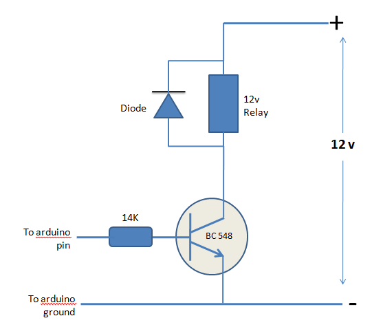
I am trying to trigger a 12 V relay with an arduino input. All I am doing in the Arduino sketch is to make pin 13 go high and low every 1 sec (1000 ms). The relay refuses to get triggered. Can someone please tell me what am I doing wrong? Struggling with this for way too long.

My circuit

enter image description here

\$\endgroup\$
5
  • \$\begingroup\$ Did you double check the transistor was good? And 14k resistor seems too weak for this. Try 1k or 2k. \$\endgroup\$
    – Passerby
    Commented Dec 26, 2014 at 15:40
  • \$\begingroup\$ The 14kohm resistor shows just how important the math for this is. \$\endgroup\$ Commented Dec 26, 2014 at 15:51
  • \$\begingroup\$ Are you sure your 12V source could get enough current for turning the relay on? \$\endgroup\$
    – Bip
    Commented Dec 26, 2014 at 15:53
  • \$\begingroup\$ possible duplicate of What determines how much current can flow through a 2N2222 A? \$\endgroup\$ Commented Dec 26, 2014 at 15:54
  • \$\begingroup\$ It looks to me like you have your 12V + and - mixed up, and your diode would be backwards if you sorted that out too. I'm surprised you haven't blown something up. \$\endgroup\$
    – Majenko
    Commented Jan 4, 2015 at 17:09

3 Answers 3

0
\$\begingroup\$

Adding to what other people said in their answers. You must ensure that the current needed to power the coil of your relay doesn't exceed BC548's maximum current rating (with a suitable safety margin).

The maximum collector current for a BC548 is 100mA, so (to be really on the safe side, even when its temperature rises), I wouldn't want to have it switch a current above, say, 50mA. If your relay needs more than 50mA of current, you should choose a BJT with a greater maximum collector current rating.

enter image description here

To check your relay current absorption connect the relay directly across a power supply (12V) and measure the current it draws from it.

\$\endgroup\$
6
  • \$\begingroup\$ I connected my relay directly to the 12 v supply. It worked nicely drawing 30mA current. I believe it does not need more than 30 mA. In that case BC 547 should still work.. right? The hfe for BC 547A is 110-200 which means that the Ib should be (0.03/150) = 0.000267 Amp. To generate that small a current, I guess I will have to put a 20K ohm resistor at the base... right? I dont have one right now with me but if these calculations look ok, I will go get one... Please do let me know. \$\endgroup\$ Commented Dec 30, 2014 at 11:00
  • \$\begingroup\$ BTW: 0.03A/150=0.0002A=0.2mA. Besides that small computation error, that is the base current that drives the BJT at the edge of the linear region (assuming an hFE=150, but you should design for the worst case, i.e. hFE=110, according to the datasheet). What you need is to switch the BJT completely ON, i.e. to drive it in full saturation independently of any other condition. This means you have to choose a base current which is much greater than that value you have computed. Say ten times bigger: Ib=2mA. This leads you to Rb=(5V-0.7V)/2mA=2.15kOhm (a standard 2.2kOhm will do). \$\endgroup\$ Commented Dec 30, 2014 at 12:35
  • \$\begingroup\$ I did the 2K ohm and I also measured the current passing through the relay. When the Arduino output is HIGH, the relay is passing 24mA current and when the Arduino output is LOW, the relay is passing 17mA current. I think as a result the RELAY is always ON ... it never switches off. I measured the potential diff between Arduino out and the Transistor base and at a HIGH, it is 11V and at a LOW it is 6V... Is my wiring wrong? Let me try posting a real picture of the wiring in my post. Any help will be much appreciated. \$\endgroup\$ Commented Dec 30, 2014 at 15:08
  • \$\begingroup\$ Maybe I don't see it well, but it seems you didn't connect the Arduino ground to your breadboard. You should connect Arduino's GND terminal to the same ground of the external 12V power supply. \$\endgroup\$ Commented Dec 30, 2014 at 15:29
  • \$\begingroup\$ Wait! I was put off track by your use of colored jumpers. You are using a red jumper to connect Arduino GND to the emitter of the BJT and an orange one to connect that terminal to the positive 12V rail, if the wiring from the 12V power supply are color-coded correctly. It seems that you got the 12V power supply rails swapped. Moreover also the diode is reversed: the cathode is the terminal with the white band. It is the other terminal (the anode) that must be connected toward the collector of the BJT. \$\endgroup\$ Commented Dec 30, 2014 at 15:38
2
\$\begingroup\$

I assume you're actually trying to drive it with an Arduino output- an input won't drive anything.

A lot of power 12V relays need around 100mA (or more) coil current. That means your base current should not be much less than about 5mA to guarantee the transistor is well saturated. If you have a 5V Arduino it might drive to 4.5V at higher current, the transistor base needs 0.7V so that's about 270uA (a lot worse if the micro is 3.3V), so it will only drive about a 5mA relay safely. From the transistor datasheet:

enter image description here

Reduce the 14K resistor to something more like (4.5V - 0.7V)/0.005 = 750\$\Omega\$ and you'll be able to drive a 100mA relay safely (assuming a 5V micro).

\$\endgroup\$
7
  • \$\begingroup\$ Thanks for sending your response. I will try again and post back but in the past I have tried using a 1K ohm resistor but each time it burns the transistor. I can try again with all calculations and post back. \$\endgroup\$ Commented Dec 27, 2014 at 3:40
  • \$\begingroup\$ @coderatlarge check you do not have the diode backwards and that the relay coil measures 120 ohms or more. \$\endgroup\$ Commented Dec 27, 2014 at 3:44
  • \$\begingroup\$ I connected my relay directly to the 12 v supply. It worked nicely drawing 30mA current. I believe it does not need more than 30 mA. In that case BC 547 should still work.. right? The hfe for BC 547A is 110-200 which means that the Ib should be (0.03/150) = 0.000267 Amp. To generate that small a current, I guess I will have to put a 20K ohm resistor at the base... right? I dont have one right now with me but if these calculations look ok, I will go get one... Please do let me know. \$\endgroup\$ Commented Dec 30, 2014 at 11:05
  • \$\begingroup\$ Relay coil measures 300 ohm. Also I have the diode correct. Still the 1K resistor did not work. \$\endgroup\$ Commented Dec 30, 2014 at 11:08
  • 1
    \$\begingroup\$ Wiring was wrong... I got it working. Thanks so much \$\endgroup\$ Commented Dec 30, 2014 at 17:46
1
\$\begingroup\$

Most likely the transistor can't sink enough current to turn on the relay. Look up how much current the relay needs with 12 V applied. Divide that by the minimum guaranteed gain of the transistor. That tells you how much base current you need. If that is more than your digital output can source, then you need more amplification in there somewhere. If the digital output can source the minimum required base current, then size the base resistor accordingly.

Figure 700 mV B-E drop in the transistor. If the digital output drives to 5 V when high, then that leaves 4.3 V across the base resistor. (4.3 V)/(14 kΩ) = 300 µA. If the transistor gain is 50, for example, then that can only support 15 mA of relay current.

Most likely your digital output can source at least 5-10 mA. A few mA base current should be possible, which should be able to support the coil current of a modest relay.
\$\endgroup\$

Your Answer

By clicking “Post Your Answer”, you agree to our terms of service and acknowledge you have read our privacy policy.

Not the answer you're looking for? Browse other questions tagged or ask your own question.