I had a board with open/collector output pins, and i need to control 2 relays syncronioulsy (open and close at the same time) with 1 open collector output. So how can make the connectıon from pin to relays?
-
\$\begingroup\$ What's wrong with simply paralleling the coils (with a catch diode if one is not otherwise provided)? \$\endgroup\$– Spehro 'speff' PefhanyCommented Dec 27, 2014 at 10:08
-
\$\begingroup\$ Mr Spehro, thanks for the response, where shuold i put the diode/s? and directly short 2 relays inputs ? , Can you share a simple connection for this (in paint may be). I couldnt figure out exactly sir. \$\endgroup\$– SosoCommented Dec 27, 2014 at 10:20
1 Answer
It will be necessary to understand the current sinking capability of the open-collector driver on the output pins. You will also need to know the off state voltage that the open-collector driver can withstand without damage. It will be necessary to not exceed either one of these parameters.
Next step is to comprehend the relay coil requirements for the two relays. How much voltage needs to be applied across the relay coil to be able to pull-in the relay and how much current flows through the relay coil when it is energized. If the two relays are the same then they can be wired in parallel. On the other hand if the two relays require different voltages you will require buffering and a separate driver stage for each relay.
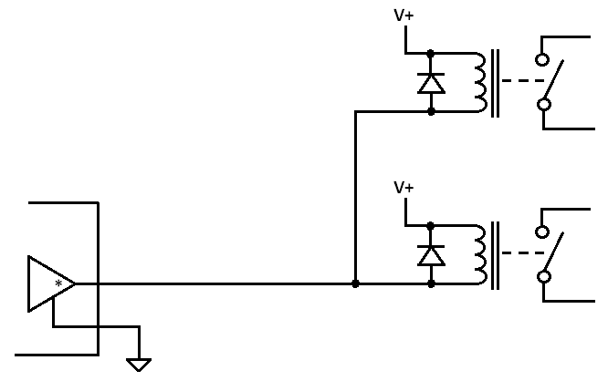
It the sum of the current for each of the two relay coils is less than the current sink capability of the open-collector output AND the relay coil voltages are the same and less than the voltage standoff rating of the open-collector output then you can connect them together as follows:

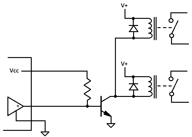
On the other hand if the rating of the output cannot meet the requirements of the relay coils then it will be required to buffer the output. This can be done various ways but here is one concept that can be used:

Component selection values need to be selected according to the current and voltage ratings of the output and the relay coils. Without detailed information being provided in the question selection cannot be specified here.
Note that it would be best to use a catch diode for each relay wired directly across the relay coil terminals.
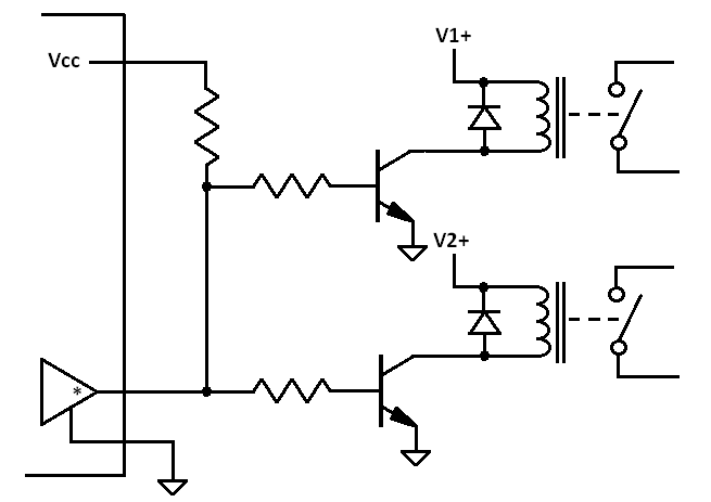
Also note that if the two relay coils operate off different voltage levels then it would be required to have two separate driver circuits, one for each relay that are wired up as follows:

-
\$\begingroup\$ First, much appreciated sir. You say : "You will also need to know the off state voltage that the open-collector driver can withstand without damage." Is that "V+" source value (in your schematic) that open collector input can handle when open state status? By the way my open collector input is around 3A, and my relays are same (max 10-20ma coil output)so i guess your first schematic is appliable for me right? Again thanks for your share Mr Karas. \$\endgroup\$– SosoCommented Dec 27, 2014 at 11:10
-
\$\begingroup\$ I cannot tell you if the first schematic is correct for you or not. For example if the relay coils require 24 VDC and the open collector output of the board can only withstand having a voltage source of 10 VDC attached to it then the first schematic would not be appropriate. \$\endgroup\$ Commented Dec 27, 2014 at 11:26
-
\$\begingroup\$ Understood. Last question: is there any relay model that production diode embedded in relay or 1 input 2 synchronize output ? \$\endgroup\$– SosoCommented Dec 27, 2014 at 11:31
-
\$\begingroup\$ Some relays are made with the catch diode built in. Relays are also commonly available with one coil controlling more than one set of switching contacts. A relay with one set of contacts is called a single pole relay. One with two sets of contacts is called a double pole relay. You can even get relays with three and four poles. Each pole of a relay can be composed of contacts that switch as Form A (a simple contact closure when the relay coil is energized) or Form C (each contact set has a common, normally closed and normally open) where one contact opens and the other closes when activated. \$\endgroup\$ Commented Dec 27, 2014 at 11:37
