0
\$\begingroup\$

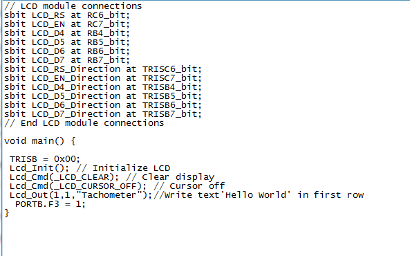
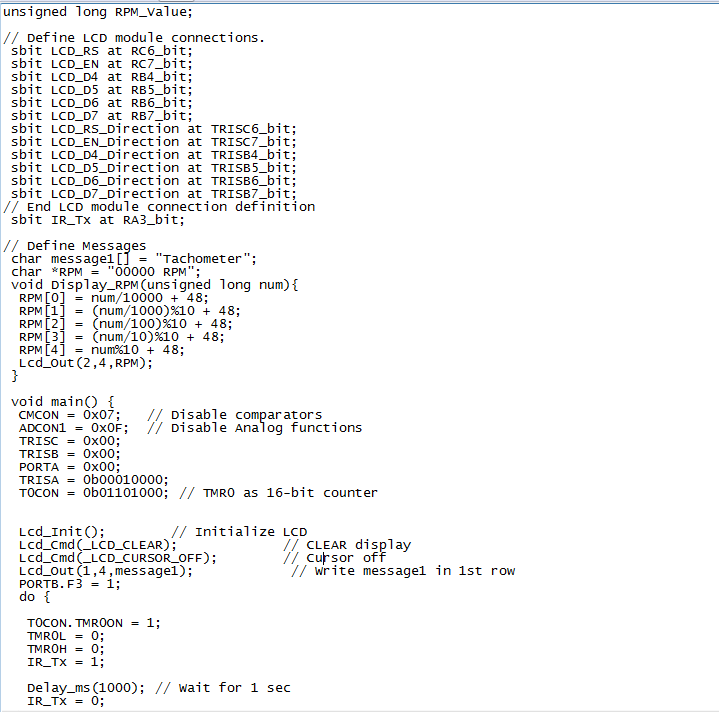
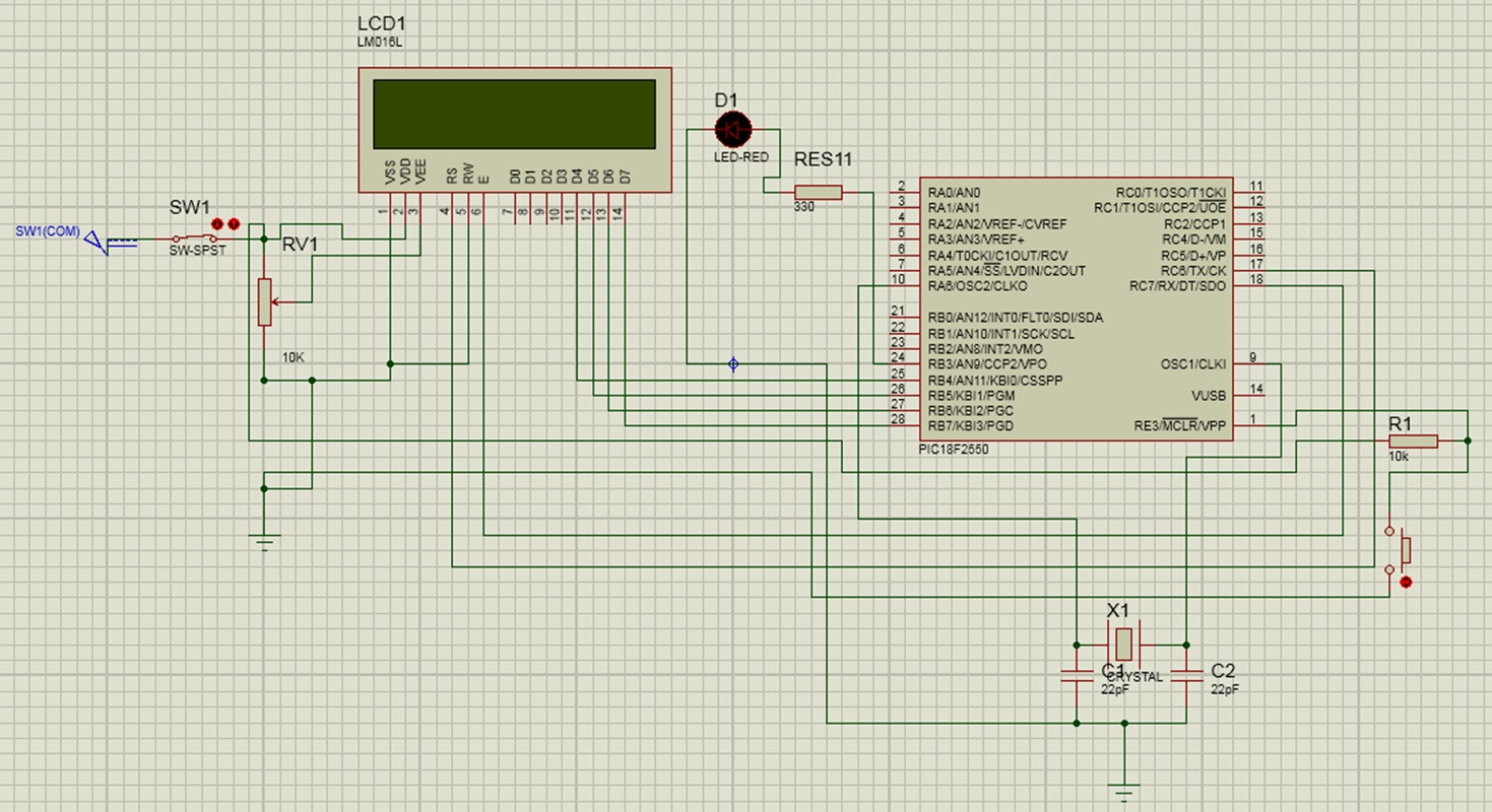
I have made circuit of contact less tachometer using PIC18F2550 micro controller. when I testing my circuit I cant get any output on LCD. But the LCD is turn on. I check all the connections one by one. Actually I cant get the helloworld output in my LCD also. The helloworld program and the tachometer programs have compiled successfully in mikroC and had desired output in proteus.So what can cause this problem.help me.

Microcontroller circuit
enter image description here

helloworld program

enter image description here

tachometer program

enter image description here enter image description here

\$\endgroup\$
8
  • \$\begingroup\$ Can you upload a higher resolution version of the schematic somewhere? It is impossible to read at the scale that it is currently. \$\endgroup\$
    – Zuofu
    Commented Jan 2, 2015 at 6:57
  • \$\begingroup\$ OK.I did the changes to my post \$\endgroup\$
    – channa
    Commented Jan 2, 2015 at 7:09
  • 1
    \$\begingroup\$ Have you checked your CONFIG bits? For example, by default, RB4 is an analog input on power up unless PBADEN is cleared. \$\endgroup\$ Commented Jan 2, 2015 at 7:23
  • \$\begingroup\$ Yes I did.I have connected RB4 pin to the D4 of LCD. Is It ok? \$\endgroup\$
    – channa
    Commented Jan 2, 2015 at 7:30
  • 1
    \$\begingroup\$ There is no good reason to include your code as pictures. Why not copy and paste it? \$\endgroup\$
    – David
    Commented Jan 2, 2015 at 8:31

2 Answers 2

1
\$\begingroup\$

When using a parallel LCD in 4-bit mode you must take care about your initialisation routine. By default the LCD will be in 8-bit mode, and you have to send it some very specific commands to put it into 4-bit mode.

You also have to worry about allowing enough delays between commands during the initialisation stage. The datasheet for the LCD will tell you what delays must be observed for any pin-state change and also for any command that is executed. Whilst debugging it would be a good idea to double these, and in practice it doesn't harm to leave them that way for the initialisation routine.

Once the LCD has initialised you have a choice about whether to use the LCD busy signal to determine when it is ready to receive data, or to use software delays. If you use the latter you must take care to follow the advice in the datasheet.

In my experience, non-working LCDs almost always boil down to incorrect delays applied in the source code.

\$\endgroup\$
0
\$\begingroup\$

Change the first six defining lines of your code to :

sbit LCD_RS at LATC6_bit; sbit LCD_EN at LATC7_bit; sbit LCD_D4 at LATB4_bit; sbit LCD_D5 at LATB5_bit; sbit LCD_D6 at LATB6_bit; sbit LCD_D7 at LATB7_bit;

Works like a treat!

\$\endgroup\$

Your Answer

By clicking “Post Your Answer”, you agree to our terms of service and acknowledge you have read our privacy policy.

Not the answer you're looking for? Browse other questions tagged or ask your own question.