2
\$\begingroup\$

enter image description here

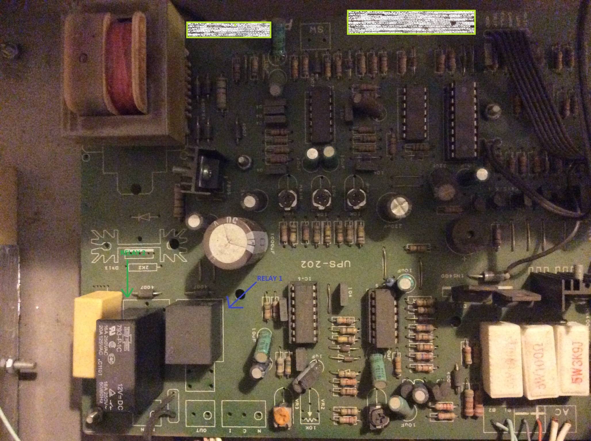
Hello I need to verify a couple of relays for proper functionality. They are soldered onto a PCB as shown in the attached image - labelled RELAY 1 and RELAY 2.

Online tutorials take a stand-alone relay and energize it via a DC power source. Can that be done here i.e. using a DC source to only apply voltage to the appropriate relay terminals while they are still soldered? What is the normal procedure for verifying relays soldered onto a PCB?

Thanks

\$\endgroup\$
1
  • \$\begingroup\$ Also: Long time socketed ICs can develop high contact resistance. Press down firmly with thumb on each end of socketed ICs. They will usually "click" and seat better (or differently). \$\endgroup\$
    – Russell McMahon
    Commented Jan 3, 2015 at 12:40

1 Answer 1

1
\$\begingroup\$

There should be no issue manually powering those relays to test them, although it looks like they have flyback diodes with them, So:

  • Be careful about the polarity you apply since the diodes (the ones labelled "4007" on the board - they'll be 1N4007 diodes) would cause a dead short if connected the wrong way.
  • The provided flyback diodes would make convenient test points for attaching your power to whilst keeping the board component side up.

Connect the + to the diode's cathode (left in the picture), and the - to the diode's anode (right in the picture) so the diode is reverse biased, and you should hear a click.

Also, you could attach a DMM to the relay's switch terminals set to continuity test, so you can observe a proper connection when it switches.

You can also use the same DMM in diode test mode as a pre-check test to confirm the diodes are functioning correctly.

\$\endgroup\$
10
  • \$\begingroup\$ mmm a few objections... applying a suitable (???) voltage to the coil will energise it, but what else will it energise? Hopefully nothing due to an o/c drive, but worth checking first. Also, putting a DMM across a flyback diode when it's in parallel with a relay coil is going to give at best a flawed reading. \$\endgroup\$
    – markt
    Commented Jan 3, 2015 at 12:38
  • \$\begingroup\$ We're not after precise readings - only an indication that the diode is functioning as it should - i.e., do the readings differ between the two orientations. \$\endgroup\$
    – Majenko
    Commented Jan 3, 2015 at 13:10
  • \$\begingroup\$ I'll post an update after following Majenko's instructions. Thanks guys. \$\endgroup\$
    – givknow
    Commented Jan 3, 2015 at 13:50
  • \$\begingroup\$ Before testing the relays, I decided to test the fly-back diodes attached above each. They both give me a reading of 0.103V when tested using a digital multimeter (DMM). All the other diodes in the circuit give a reading of around 0.55 V. Is the 0.103 V reading abnormal? Is it safe to conclude these diodes have broken down? Or could it be that somehow, proper electrical contact between the DMM probes and the diode's end is not being made? Thanks \$\endgroup\$
    – givknow
    Commented Jan 4, 2015 at 15:56
  • \$\begingroup\$ It may be that the coil in the relay is overpowering the reading of the diode. Try testing with a low powered and slightly under-voltage power source observing the orientation of the diodes. For 12V relays try a small 9V PP3 battery. \$\endgroup\$
    – Majenko
    Commented Jan 4, 2015 at 15:59

Your Answer

By clicking “Post Your Answer”, you agree to our terms of service and acknowledge you have read our privacy policy.

Not the answer you're looking for? Browse other questions tagged or ask your own question.