1
\$\begingroup\$

I am using the LTC3388-1 buck converter to provide a microcontroller with a regulated 1.8V voltage. I use pretty much the reference circuit as seen in the image.
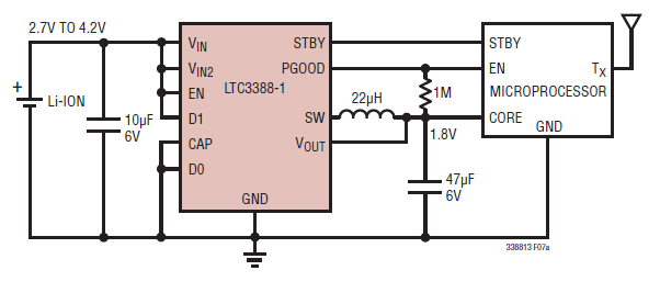
reference circuit

When I disconnect the microcontroller (remove the wire CORE as seen in the image), I measure 1.8V in the output of the converter.

When I apply a resistor as load, the output voltage is again stable at 1.8V. As I decrease the resistance of the load resistor, the current increases, until it reaches 50mA (the maximum supported by LTC3388-1). Then, the voltage starts to drop.

So far so good.

When I connect the microcontroller (as seen in the image), I measure 0.6V at Vout. The current is also low at approximately 10uA; nowhere close the maximum limits of the converter.

Figure below shows the behaviour of the system when I connect the MCU.
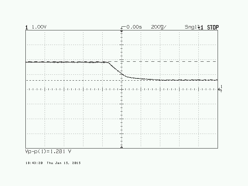
behaviour

What can possibly cause this voltage drop?

\$\endgroup\$
8
  • 1
    \$\begingroup\$ 0.6V is a silicon diode drop. Are you sure the MCU is working? \$\endgroup\$ Commented Jan 15, 2015 at 14:29
  • \$\begingroup\$ The MCU is not flashed with anything. Default factory settings. In case it helps, if I apply 1.8V to the MCU directly from a power supply (bypassing completely LTC3388-1), I measure a current of 2-3mA (which kinda makes sense). \$\endgroup\$
    – user45350
    Commented Jan 15, 2015 at 14:34
  • \$\begingroup\$ What does the PGOOD output indicate? It needs a pull up BTW. \$\endgroup\$
    – Andy aka
    Commented Jan 15, 2015 at 14:51
  • 1
    \$\begingroup\$ What microcontroller is it? It seems to behave similar to a 0.6V zener in its current role. When you connect the resistor, what value does it have and how are the pins usually connect to the mc connected? What is the input voltage (and does it drop?) what values do the other components have (i and c Rser)? When you are doing measurements with the scope you might want to attach some images. The more information you provide, the more chance you have that someone spots something unusual. \$\endgroup\$
    – PlasmaHH
    Commented Jan 15, 2015 at 16:31
  • 1
    \$\begingroup\$ MCU is nRF51822 (it has an embedded ARM cortex M0). I tried load resistors from few K down to 10 ohm and everything behaved normally. Voltage dropped only when I exceeded the 50mA. Input voltage is 3V3 and it never drops in all experiments. What particular scope picture might be interesting? I don't want to spam it with irrelevant images. \$\endgroup\$
    – user45350
    Commented Jan 15, 2015 at 16:44

2 Answers 2

2
\$\begingroup\$

Mystery solved.

Problem was caused by the STBY pin of the converter.

This STBY pin puts the converter in standby mode. 1 = standby and 0 = on. When the MCU is powered off, the floating pin is interpreted as 0 and everything works fine (V=1V8).

I am not sure what is the factory default configuration of the MCU, but it seems that when the it is powered on, the STBY pin is interpreted as 1 from the converter, essentially turning the converter off. This leads to the converter going on and off continuously.

I verified this theory by grounding the STBY pin manually, with the MCU connected, and the voltage went up to 1V8 (with current at 2-3mA).

\$\endgroup\$
0
0
\$\begingroup\$

Be sure you are using the correct type of 47uf and 10uf cap (as per the data sheet)

Check if the output voltage is oscillating. This might be caused by the wrong cap type, the wrong cap placement, or maybe the chip cannot supply very low currents. What happens if you place an extra resistor to ground from the 1.8v output?

There is a condition that may require an RC network on Vin. (eg. A long input wire.)

See page 14 of the spec sheet for more ideas, http://cds.linear.com/docs/en/datasheet/338813f.pdf

\$\endgroup\$
7
  • \$\begingroup\$ Datasheet says: In applications where the input source is limited to 6V, the CAP pin can be tied to the GND. \$\endgroup\$
    – user45350
    Commented Jan 15, 2015 at 15:22
  • \$\begingroup\$ I also put a 470 Ohm resistor in parallel with the MCU. Voltage still 0.6V and I see a normal current of 1.3mA (=0.6/470). \$\endgroup\$
    – user45350
    Commented Jan 15, 2015 at 15:23
  • \$\begingroup\$ OK, on CAP pin to GND. \$\endgroup\$
    – Nedd
    Commented Jan 15, 2015 at 15:31
  • \$\begingroup\$ Just checked the oscillation. I get a peak-to-peak oscillation of 50-60mV. Seems in line with all the oscilloscope pictures in the datasheet. When MCU disconnected the period of oscillation is 2.5 seconds. When MCU is connected (10uA), I get a period of 100ms. \$\endgroup\$
    – user45350
    Commented Jan 15, 2015 at 15:39
  • \$\begingroup\$ I don't think it's the long wire. I just replaced it with a battery socket (~1cm of feed line) and the behaviour looks the same. \$\endgroup\$
    – user45350
    Commented Jan 15, 2015 at 15:44

Your Answer

By clicking “Post Your Answer”, you agree to our terms of service and acknowledge you have read our privacy policy.

Not the answer you're looking for? Browse other questions tagged or ask your own question.