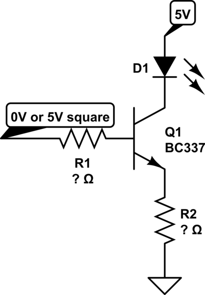
I am trying to make an IR transmitter, and have the following set up:

simulate this circuit – Schematic created using CircuitLab
I was thinking of this circuit, because I want to run through the LED ~700mA with 20mA output from the microcontroller. And putting R2 at the collector would mean a lot of power wasted by R2, doing this I am hoping to minimize that.
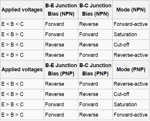
However the problem is I want to put the BJT into saturation mode of operation using this configuration. I found this table on wikipedia, that shows what voltages should be applied to what contant for different modes of operation:
I can understand the table, but have problems calculating the resistor values. Here's what I do know (for saturation):
- Q1 collector current \$I_c=700mA\$
- D1 voltage drop \$V_f=1.4V\$
- Q1 CE voltage drop \$V_{CE}=0.3V\$
- Q1 BE voltage drop \$V_{BE}=0.95V\$
Using these values how can I calculate resistors needed to put the transistor into saturation mode of operation?
Could you provide more general details about the calculations, that could work for any mode of operation.


