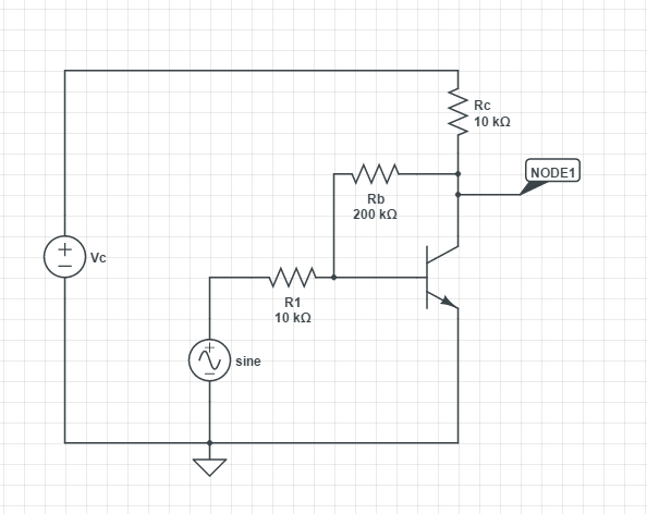
This exercise is about a BJT transistor common emitter circuit, with a biasing resistor between the base and the collector. I am supposed to compute the signal amplification of the circuit \$V_o/V_s\$ (\$V_o\$ being at node1). I am given that the transistor has \$\beta = 50\$ and \$r_{\pi} = 1.1\$ for the \$\pi\$ equivalent model.

-
1\$\begingroup\$ What work have you done so far? Also, your value of \$r_{\pi}\$ seems low. Is that supposed to be in k\$\Omega\$? \$\endgroup\$– Null ♦Commented Jan 24, 2015 at 16:55
-
\$\begingroup\$ Yes I'm sorry it is. I have drown the equivalent circuit with the pi model i just don't know where to put Rb, as part of the input or output? \$\endgroup\$– user3401Commented Jan 24, 2015 at 16:59
-
\$\begingroup\$ Do you have some knowledge about negative feedback? \$\endgroup\$– LvWCommented Jan 24, 2015 at 17:02
-
\$\begingroup\$ not really, i am a second year student, just getting started with electronic \$\endgroup\$– user3401Commented Jan 24, 2015 at 17:03
-
\$\begingroup\$ General: Pi model would need dragging out of memory and dusting off but this is general approach: Assume Z_AC source = 0 for DC. For model used, establish DC operating point. Establish Rbe internal from current.Solve. \$\endgroup\$– Russell McMahon ♦Commented Jan 24, 2015 at 20:44
2 Answers
There are, in principle, two ways for solving the task. Please understand that I do not intent to present the solution for you. However, I will try to give you some hints to find the solution by yourself.
1.) Application of the superposition theorem
Supplementing the transistor Pi-model with the external resistors results in a circuit which contains two sources: A voltage source Vin and the controlled current source of the Pi-model. Thus, after applying the superposition principle you get two equations for finding the two unknown quantities: Vo/Vin and Vbe. (Please note that the transconductance of the Pi-model can be expressed by the two known values for beta and Rpi).
2.) Application of the general gain formula for negative feedback
The closed-loop gain is Vo/Vin=Acl=AoHf/(1-AoHr). (Note that Ao will be negative).
Gain without feedback Ao=Vout/V(base) (simple gain formula for common emitter);
Forward (damping)factor Hf=V(base)/Vin for Vout=0;
Return (feedback) factor Hr=V(base)/Vout for Vin=0.
Both factors are calculated using simple voltage divider rules.
-
\$\begingroup\$ This transistor circuit exploits the same idea (parallel negative feedback) as the op-amp inverting amplifier. \$\endgroup\$ Commented Aug 18, 2017 at 6:04
You can take the Rb and connect it directly between the base and VC and denote it as Rb+Rc. Then the circuit simplifies a great deal and then you can use the two variable method specified by LvW.
