1
\$\begingroup\$

I'm trying to use an Arduino+transistor to control a shutter (which I believe is a solenoid) at work. The shutter is normally connected to a power supply by two small wires (positive and negative) and from what I've gathered with my DMM an 11.3 V 3.8 mA current is applied to the shutter to keep it closed, and when it is opened the voltage and current drop to 0 before reapplying the current to close it again.

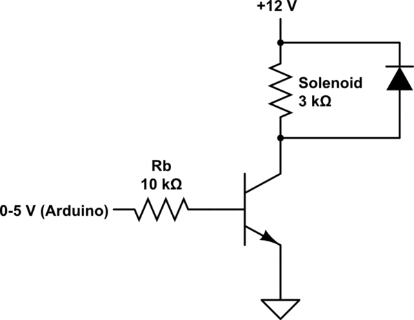
Right now I have the following circuit configured so that the transistor base is connected to the PMW 9 pin on the arduino, which cycles between 5 seconds of output = HIGH (5V) and output = LOW (0V). What confuses me the most is that when I take measurements with my DMM I get roughly the same results (12V and 4mA) on the solenoid but the shutter doesn't close.

Any thoughts? Is there something I'm missing in my circuit? The only thing I can think of is that maybe the current isn't ramping up fast enough to induce a noticeable magnetic force (I think that's how it works, don't judge me I haven't taken emag in a while), but I don't know how I'd be able to combat this. Thanks.

My circuit http://www.docircuits.com/circuit-simulation-public/12041

If my circuit isn't clear enough (mostly in the arduino area) leave a comment and I'll try to clear things up.

EDIT: I realize now that the arduino is actually sending a pulse-width modulated signal with duty cycle of 100%. Could this be causing problems?

EDIT2: Updated the schematic.

\$\endgroup\$
10
  • 1
    \$\begingroup\$ Your diode is upside down \$\endgroup\$
    – Mike
    Commented Jan 27, 2015 at 16:28
  • 1
    \$\begingroup\$ Tip for schematics: it's a lot easier to read circuits where power (like your 12 V source) travels from top to bottom and signals travel from left to right. This is part of what Olin means about "things being sideways." \$\endgroup\$
    – Greg d'Eon
    Commented Jan 27, 2015 at 16:40
  • 1
    \$\begingroup\$ @OlinLathrop, I'm sorry if this was not the place for the question, but I had found other related questions involving using arduinos to control motors on ee.se so I thought it was appropriate. And I feel as though outright closing the question is a bit harsh, I tried to supply as much information as I could and drew the schematic in the same way that I have it. I'm sorry if this question was not up to par, I am by no means an electrical engineer but rather just someone looking for a little bit of advice with regards to something that I thought would be a simple problem. \$\endgroup\$
    – wes3449
    Commented Jan 27, 2015 at 16:41
  • 2
    \$\begingroup\$ This is a very appropriate place for your electronic circuit design question. Feel free to ignore Olin's notoriously habitual abuse, or change Arduino to ATmega328p to make it irrelevant, as the "Arduino" aspect was never important to begin with. \$\endgroup\$ Commented Jan 27, 2015 at 19:36
  • 1
    \$\begingroup\$ On the technical front, is there any chance your actuator incorporates a permanent magnet and so requires a particular polarity? Will jumpering across the transistor close it? Is the transistor in backwards? \$\endgroup\$ Commented Jan 27, 2015 at 19:38

3 Answers 3

1
\$\begingroup\$

It looks like there are some issues with your circuit. Summing up the comments:

  • Your diode has the wrong polarity to stop back-emf
  • Your base resistor is too large

Here is an updated schematic with these fixes.

schematic

simulate this circuit – Schematic created using CircuitLab

You could also take a look at this answer to see a bit more info on driving a solenoid.

\$\endgroup\$
3
  • \$\begingroup\$ I've made the suggested changes but still no dice. I can clearly see the voltage across the solenoid switch from 0 to ~12 V and the current from 0 to ~4 mA every 5 seconds yet the shutter just won't click. Also it turns out that the arduino is sending a pulse-width modulated signal. Could that be the root of the problem? Thanks. \$\endgroup\$
    – wes3449
    Commented Jan 27, 2015 at 17:05
  • 1
    \$\begingroup\$ I don't think the frequency of the PWM signal is the problem otherwise the current would be lower and that's not the case according to your measurements. Questions: What kind of shutter is this 4mA x 12V = 48mW. This looks small too me. What instrument do you use to measure the current? \$\endgroup\$
    – Ambiorix
    Commented Jan 28, 2015 at 0:16
  • \$\begingroup\$ @Ambiorix I used a simple DMM connected in series with the shutter to measure the current. I agree that it seems rather low, perhaps the initial current is much higher but the resolution of the DMM isn't good enough to catch the spike... \$\endgroup\$
    – wes3449
    Commented Feb 13, 2015 at 16:07
1
\$\begingroup\$

If the Arduino is sending a PWM signal that could be the problem. However, you say it is PWM with 100% duty cycle, which would be on all the time, which is the same as a DC signal. Is it on and off the same amount of time? That would be 50% duty cycle.

If you have the same current through the coil you should have the same magnetic field and pull strength. The rise rate doesn't affect that.

\$\endgroup\$
1
  • \$\begingroup\$ I switched it over to a non-PWM pin just to be safe and the result is the same. I feel like maybe when the solenoid is turned on there's an initial current spike well above the normal 4mA, but I don't really see how I'd be able to control that with the transistor anyways. \$\endgroup\$
    – wes3449
    Commented Jan 28, 2015 at 13:53
1
\$\begingroup\$

Have you got the solenoid wired the right way around? Some relays, which is really a solenoid connected to pull a switch have polarity for their coils, this solenoid could be the same.

\$\endgroup\$

Your Answer

By clicking “Post Your Answer”, you agree to our terms of service and acknowledge you have read our privacy policy.

Not the answer you're looking for? Browse other questions tagged or ask your own question.