3
\$\begingroup\$

I am new in this kind of stuff so please excuse me for my lack of knowledge. I have successfully connected blackwidow (wifi + arduino) with a relay to control a 220V light bulb.

Now, I want to embed all this circuitry in my room for each and every socket. The problem is that I don't want to remove my physical switches from the wall. I want them to be there and always function normally.

How should I connect both elements so that I can control the lighting from both the switches?

  • Arduino hardware
  • Physical switch which has been there for a long time

And how can I achieve the following?

  • Turn on the light with the physical switch, then turn off the same by my android which is connected to the blackwidow via local network
  • and vice versa

Thanks in advance

\$\endgroup\$
2
  • \$\begingroup\$ Physical Switch? Are you referring to a normal light switch that is usually mounted on the wall? \$\endgroup\$
    – Dean
    Commented Jun 15, 2011 at 9:03
  • \$\begingroup\$ yes the one which is mounted on the wall \$\endgroup\$ Commented Jun 15, 2011 at 11:25

3 Answers 3

2
\$\begingroup\$

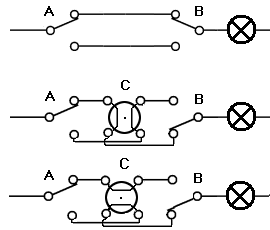
If you want to control a light from 2 points you need the following circuit (the top one):

enter image description here

Chances are that your current switch is just on/off (SPST or Single Pole Single Throw) instead of the SPDT (Single Pole Double Throw) switch used in the diagram. You really need the SPDT, but you use it just like the other one. The second switch (B) is your relay, which also has to be SPDT.
If you want to switch from 3 or more points you need the center circuit. Switch A and B remain the same, but you need switch C (repeat C for every additional switch). The center and bottom circuit are the same, they just show switch C in both their states.

\$\endgroup\$
6
  • \$\begingroup\$ Note that you not only have to replace the switch, you'll also have to do some serious rewiring! \$\endgroup\$ Commented Jun 15, 2011 at 9:36
  • \$\begingroup\$ @Federico - Right! \$\endgroup\$
    – stevenvh
    Commented Jun 15, 2011 at 9:38
  • \$\begingroup\$ Thanks guys this is a bit too much for me. I will take some time to dig in deeper and understand what ya all have suggested and post back my experience. But in the mean time all i want to know that is this a practical and reliable approach which i am using or should i completely move on some other track to go for home automation?? \$\endgroup\$ Commented Jun 15, 2011 at 11:08
  • \$\begingroup\$ @Abhishek - Don't be discouraged if this looks complicated. Adding home automation to an existing installation where you don't want to change much usually becomes complex. In a home automation system built from the ground up the switching will be done by a single relay, for instance, and controlled by pushbuttons on a bus (or wireless). \$\endgroup\$
    – stevenvh
    Commented Jun 15, 2011 at 18:39
  • \$\begingroup\$ The only thing i cant get now is switch C. If you could please explain a bit more or may b a link to some one done this before it would be really helpfull thanks \$\endgroup\$ Commented Jun 16, 2011 at 19:42
2
\$\begingroup\$

Sorry to revive an old topic, but I've been thinking about the problem of wiring like this WRT the home automation not knowing if the light is on or off.

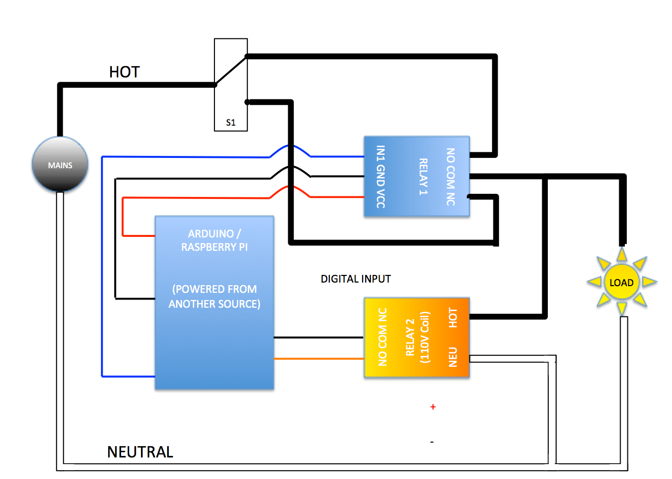
I think I may have come up with a solution. 110V Coil relays are now dirt cheap. What if the 5V DC Coil Arduino/Pi/Whatever controlled relay was paired with a 110V AC Coil relay. Installation of this is done near the fixture, not the switch.

Basically you'd wire the whole thing up exactly the way stevenh has shown (either 3 way or 4 way setup will work) but just before the load you'd split off the hot wire and connect it to the 110V relay's coil. (Obviously attaching the neutral to the other side of the relay's coil.)

Then from the N.O. contacts on the 110V relay you would attach it to your Arduino/Pi/Whatever as a digital input. This way when the loads are receiving power, the low voltage circuit attached to the 110V relay will be closed. And when the power has been turned off (either through the automation or manually) the low voltage circuit will be open.

It seems so simple (so I must be missing something).

I've done a VERY rough drawing of what I mean.Rough Schematic - Home Automation Readable Bypass

\$\endgroup\$
-1
\$\begingroup\$

You're out of luck I'm afraid my friend. Which ever way you go about it will require some re-wiring or replacing of the physical switch and its cable.

As the other answer shows, you can achieve it with two-way switches and cabling, but as it says you will probably not have this in situ, so you will need to re-wire it and replace the switch with a SPDT type.

The other way to do it would be to replace the wall switch with a push-button type (you can get them that look like a switch but don't stay in the 'on' position), which connects to an input (not using mains) on the Arduino to toggle the light relay. This will also allow you to get some feedback from the Arduino as to the real status of the light and toggle it on and off properly.

\$\endgroup\$
4
  • \$\begingroup\$ I don't know about regulations in other parts of the world, but European regulations forbid mains and SELV (Separated Extra Low Voltage) wiring in the same tube. \$\endgroup\$
    – stevenvh
    Commented Jun 15, 2011 at 9:32
  • \$\begingroup\$ @stevenvh It's also a bad idea in general from an inducted EMF point of view - should be avoided on general principle wherever possible. \$\endgroup\$
    – Majenko
    Commented Jun 15, 2011 at 9:34
  • \$\begingroup\$ So u mean to say that this approach will not be good for long run ?? \$\endgroup\$ Commented Jun 15, 2011 at 11:25
  • \$\begingroup\$ The approach is good - it's the combining of signal and mains power cables in the same trunking that is bad - so you may have some problems running your signal cables. \$\endgroup\$
    – Majenko
    Commented Jun 15, 2011 at 11:32

Not the answer you're looking for? Browse other questions tagged or ask your own question.