I'm trying to create a data logger. I want the data logger to be able to run in 2 modes.
- Bench mode (USB powered 5 V)
- Field mode (externally powered 3.3 - 12 V)
Bench mode is active whenever power is supplied to the USB port. In the other case Field mode is active. I want this because the data logger will be used in battery powered projects and I don't want the data logger to leech from the host project if it can get its power from USB.
So basically I want to create a power multiplexer that switches the external power supply off whenever USB power is supplied.
The datasheet of the micro controller I'm planning to use gave the following schematic.
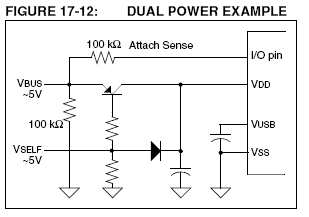
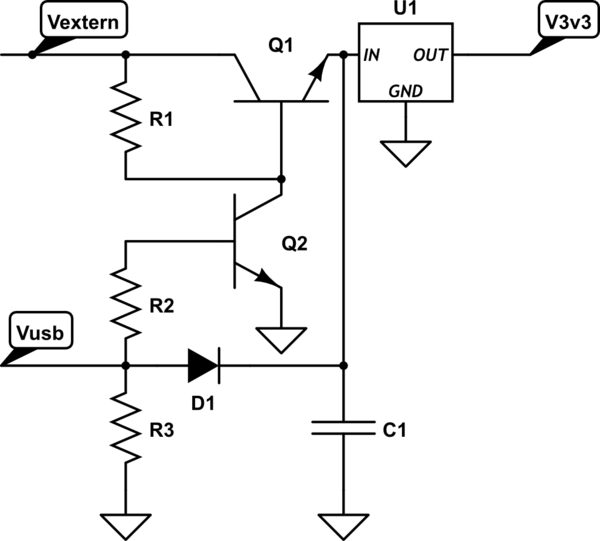
The working thou is exactly opposite of what I had in mind, so I tried to adjust it. I know this should work as long as the external power supply is lower the 6-7 V, but what about higher voltages?
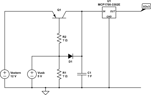
simulate this circuit – Schematic created using CircuitLab
Note: Only an example.
Either configuration should have an as low as possible current consumption, and a small footprint.
I have seen a lot of topics related to this but they haven't given me the answer how to do it.
So my question(s):
- Is it possible?
- How can I switch off a 3.3 V - 12 V power supply using USB power supply?
- How to determine needed resistor / capacitor values?
- Which parts would you recommend?
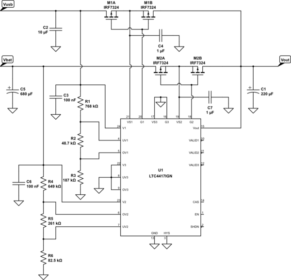
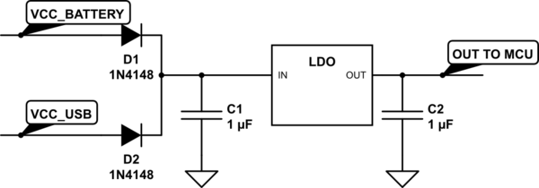
thou ORing is an option it doesn't prevent my circuit (behind the LDO) to leech from the host project.
I also understand the restrictions set by the USB standard.
I probably should use MOSFETs instead of BJTs but I wonder if this would work.
