8
\$\begingroup\$

I'm working with the Venus 634FLPx GPS chip.

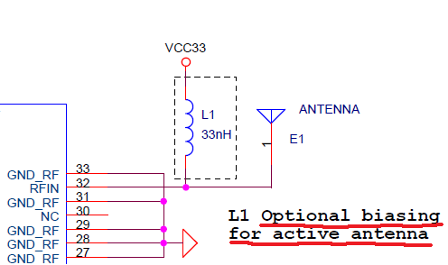
The reference schematic in the datasheetincludes an inductor L1 marked "optional biasing for active antenna":

enter image description here

What is biasing, what makes an antenna active, why is it optional, why would I opt to include or exclude it?

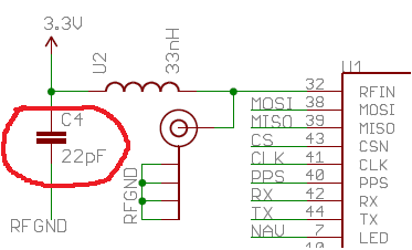
SparkFun supplies a breakout board for this unit which includes this inductor in its schematic. Interestingly, it also includes a 22pF capacitor between the high side of the inductor and the RF ground:

enter image description here

I assume this capacitor is for power supply decoupling? Or does it serve some other purpose?

\$\endgroup\$

3 Answers 3

5
\$\begingroup\$

"Biasing" in this context basically means: to provide power to the active antenna

Active GPS antennas have a built-in amplifier (you'll see the term LNA floating around, Low Noise Amplifier), near the actual antenna element. The signals from GPS are so small that losses from a long (~10cm or more) wire are incredibly detrimental to the signal.

For any amplifier to work, it needs power (a positive and a return, aka ground). Most GPS connections use SMA connectors, and they only have 2 pins. One for ground, and one for "data". So how do you "send power" to the amplifier that is built into the active GPS receiver when we don't have an extra power pin? This is where the inductor comes in - it's a trick to share the positive power line with the GPS "data" signal line.

This works because the GPS data is completely AC data. The inductor decouples the output signal from the high impedance positive power rail, allowing the output signal's AC component (the actual GPS RF data) to come back along the power line. Or another way to say it, prevents the power rail from washing out the signal that we care about.

And yes, that extra 22pF capacitor is just to help provide clean (low noise) power to the inductor. If there is extra noise on the power line, that noise can get through the inductor and wash out the GPS signal that you care about.
\$\endgroup\$
1
  • \$\begingroup\$ This is truly a fantastic explanation. I am working on trying to understand this and this is the best I have seen. Thanks so much. \$\endgroup\$
    – ril3y
    Commented Jun 16, 2023 at 20:51
3
\$\begingroup\$

Wikipedia defines active antenna as an antenna module that contains an amplifier. The purpose of the L and C would most likely be to provide filtered, clean DC to the amplifier section.

\$\endgroup\$
2
  • \$\begingroup\$ Do you think this means that something bad would happen if the inductor connection was present and someone mistakenly attached a passive antenna? \$\endgroup\$ Commented Jun 21, 2011 at 18:23
  • 1
    \$\begingroup\$ The passive antenna would be energized to 3.3V, and could potentially short out the battery if it were to make contact with the low-side somehow. I would expect that the active antenna amplifier circuitry would block the DC from going up the antenna itself. \$\endgroup\$ Commented Jun 21, 2011 at 18:59
2
\$\begingroup\$

The inductor is a choke to isolate the antenna from the bias supply. The capacitor is for decoupling the cold end of the choke.

\$\endgroup\$

Your Answer

By clicking “Post Your Answer”, you agree to our terms of service and acknowledge you have read our privacy policy.

Not the answer you're looking for? Browse other questions tagged or ask your own question.