3
\$\begingroup\$

I'm confused about a passage in "The Art Of Electronics", by Horowitz & Hill, regarding protective diodes in transistor switches:

2. If the load swings below ground for some reason (e.g. it is driven 
   from ac, or it is inductive), use a diode in series with the collector
   (or a diode in the reverse direction to ground) to prevent 
   collector-base conduction on negative swings.

3. For inductive loads, protect the transistor with a diode across the 
   load....

My problems with the above two points are:

  1. Why would/how could the load be "driven by ac"? Wouldn't an ac load pull the collector below ground and thus turn off the transistor on the negative part of the ac cycle? Moreover, how could the load be driven by ac when by construction we're sending a DC current through it?!

  2. I'm having trouble parsing the phrase "use a diode in series with the collector (or a diode in reverse direction to ground)". The language is somewhat ambiguous: does the "or" mean "in other words", or does it mean "alternatively". If the latter, why would you want a diode in the direction of Vcc to ground? If the former, then if I change the phrase to: "use a diode in series with the collector, directed from ground to Vcc", am I changing the meaning? Because that's actually how I understand the phrase!

  3. Bullet points 2 and 3 are very similar. In fact, their conceptual "triggers" overlap, i.e. for "inductive loads", but they suggest different things. For 2 the suggestion is a diode in series with the load (pointing to Vcc) and in 3 the diode is in parallel (again pointing to Vcc). How should I choose between the two? Can someone give an example of an inductive load in which the diode is to be applied in series rather than in parallel? (There is an example for point 3 in the book, but alas not point 2.)

Following is a diagram of what I believe to be the schematic implied by Horowitz point 2. It has been confirmed to be correct by experts.
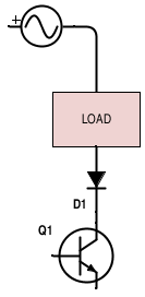
Point 2 in Horowitz

\$\endgroup\$
3
  • \$\begingroup\$ The answers below cover this, but I wanted to mention the high-level difference between the two statements: point 2 is more for sustained reversed polarities while point 3 is for high-voltage transients. \$\endgroup\$
    – Dan Laks
    Commented Mar 10, 2015 at 17:07
  • \$\begingroup\$ Could someone please confirm whether my proposed schematic for point 2 is correct? Many thanks! \$\endgroup\$
    – seertaak
    Commented Mar 11, 2015 at 19:02
  • \$\begingroup\$ The schematic is correct for a NPN transistor. \$\endgroup\$ Commented Mar 11, 2015 at 19:26

2 Answers 2

1
\$\begingroup\$
  1. It is perfectly valid to run AC through a BJT between collector and emitter. What happens is the BJT will (should) act as a rectifier, conducting for only half of the period.

  2. The B-C junction of a BJT is a P-N junction, hence it can become forward biased if the collector voltage goes lower(NPN)/higher(PNP) than the base voltage. You do not want this to happen, therefore you put a diode in series that will become reverse biased when the B-C junction becomes forward biased.

  3. The flyback diode protects the transistor by preventing VCE from breaching its maximum, whereas the series diode prevents the transistor from conducting in a degenerate mode when switching an AC voltage.

\$\endgroup\$
2
  • \$\begingroup\$ Thanks for your answer, which I accepted because it was short and clear. But: "put a diode in series that will become reverse biased when the B-C junction becomes forward biased" -- so for a pnp transistor, you would add a series diode pointing to ground, right? Why then does the text mention "in the reverse direction to ground", which to me sounds like pointing to Vcc? \$\endgroup\$
    – seertaak
    Commented Mar 11, 2015 at 12:30
  • \$\begingroup\$ @seertaak: AC doesn't have a Vcc, it has a positive peak and a negative peak. You want to make sure that the voltages that can forward bias the B-C junction are clipped. \$\endgroup\$ Commented Mar 11, 2015 at 13:44
2
\$\begingroup\$
  1. An NPN BJT will conduct significantly from collector to base (it is a junction) if the collector is brought below the base voltage by more than a few hundred mV. That could cause problems.

  2. Either block the voltage (series diode) or conduct it to ground. In one case the compound switch is 'open' for voltages << 0V, in the other case it conducts. Depends on what you want. If you want to switch both sides of the AC you need to do something a bit different.

  3. You do not normally put a diode in series with an inductive load. In the case of an inductive load you need to provide a path for the current to flow when the switch turns off, in order to allow the energy stored in the inductor to dissipate, and that path is typically provided by some kind of network in parallel with the inductor- a diode, a diode with a zener in series, a bipolar TVS, an RC snubber, that sort of thing. If you put a diode in series with a pure inductive load, switching the driver off would result in the diode breaking over in reverse as the voltage rose to some very high value. In practice that might not happen- for example, you could probably safely put a 3kV diode in series with a 3V relay because the coil voltage would never get to more than a few hundred volts due to the coil distributed capacitance, but it's hard on the coil insulation. The only advantage it would have is that it would allow the coil field to collapse very quickly (oh, and the high voltage might be a useful side effect in some cases).

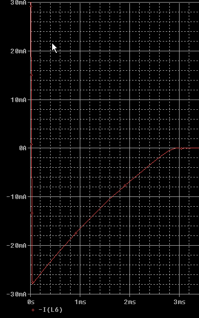
Edit: Re below question about what happens with series diode- here is a simulation- the switch does not permit voltage to fall below zero, otherwise you get a relatively slow ring-down.

enter image description here

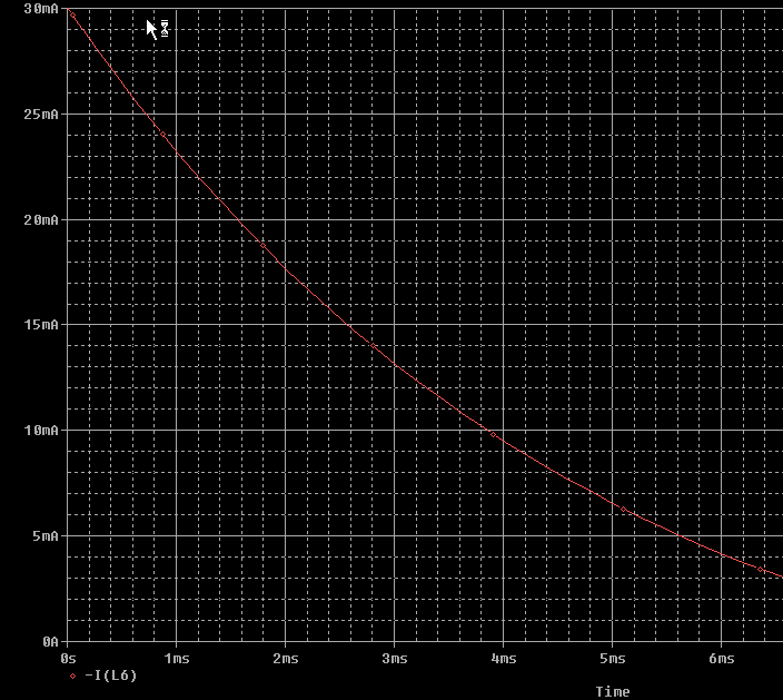
Now with a parallel diode:

enter image description here

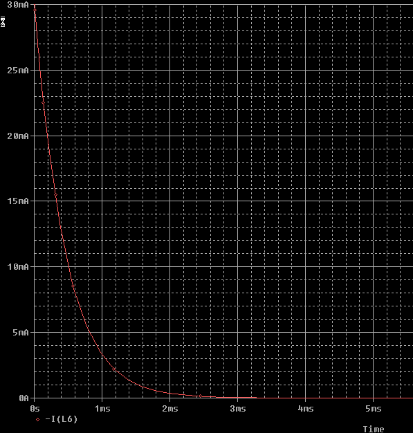
1K in parallel with coil, series diode and no limitation on switch voltage:

enter image description here

\$\endgroup\$
8
  • \$\begingroup\$ How would a 3kV series diode allow the coil field to collapse quickly if no breakdown occurs? \$\endgroup\$
    – sherrellbc
    Commented Mar 10, 2015 at 17:38
  • \$\begingroup\$ You'll get 1/2 cycle of ringing with the distributed capacitance (assuming the switch doesn't allow the output voltage to go below zero) then - depends on the limitations of the circuit- voltage below zero, parallel resistance etc.. See my edit above. C = 200pF, L = 0.5H, R = 100\$\Omega\$. Ideal case with a switch that opens up completely and plausible coil values is a nasty high-voltage high frequency but slow envelope ring-down. \$\endgroup\$ Commented Mar 10, 2015 at 19:12
  • \$\begingroup\$ "will conduct significantly from collector to base ... if the collector is brought below the base ..." -- shouldn't you write "...conduct significantly from base to collector"? Because I thought one assumes conventional current and therefore things conduct from positive to negative. And if the collector is brought below the base, then surely the current flows from base to collector. Am I misunderstanding something, or can the word "conduct" be used commutatively? \$\endgroup\$
    – seertaak
    Commented Mar 11, 2015 at 18:14
  • \$\begingroup\$ @seertaak I'm not implying the direction of current flow, only that it's between those two nodes. As you correctly point out, with an NPN transistor the current would be flowing out of the collector. \$\endgroup\$ Commented Mar 11, 2015 at 18:16
  • \$\begingroup\$ Just to clarify nomenclature a bit more. If I write: "use a diode in series with the collector", am I implying (without any other information) that the diode goes in the same direction as the conventional current? So am I implying that the diode points from the collector "towards" the emitter? \$\endgroup\$
    – seertaak
    Commented Mar 11, 2015 at 18:23

Your Answer

By clicking “Post Your Answer”, you agree to our terms of service and acknowledge you have read our privacy policy.

Not the answer you're looking for? Browse other questions tagged or ask your own question.