0
\$\begingroup\$

I'm building a power supply, based on this instructable and this one
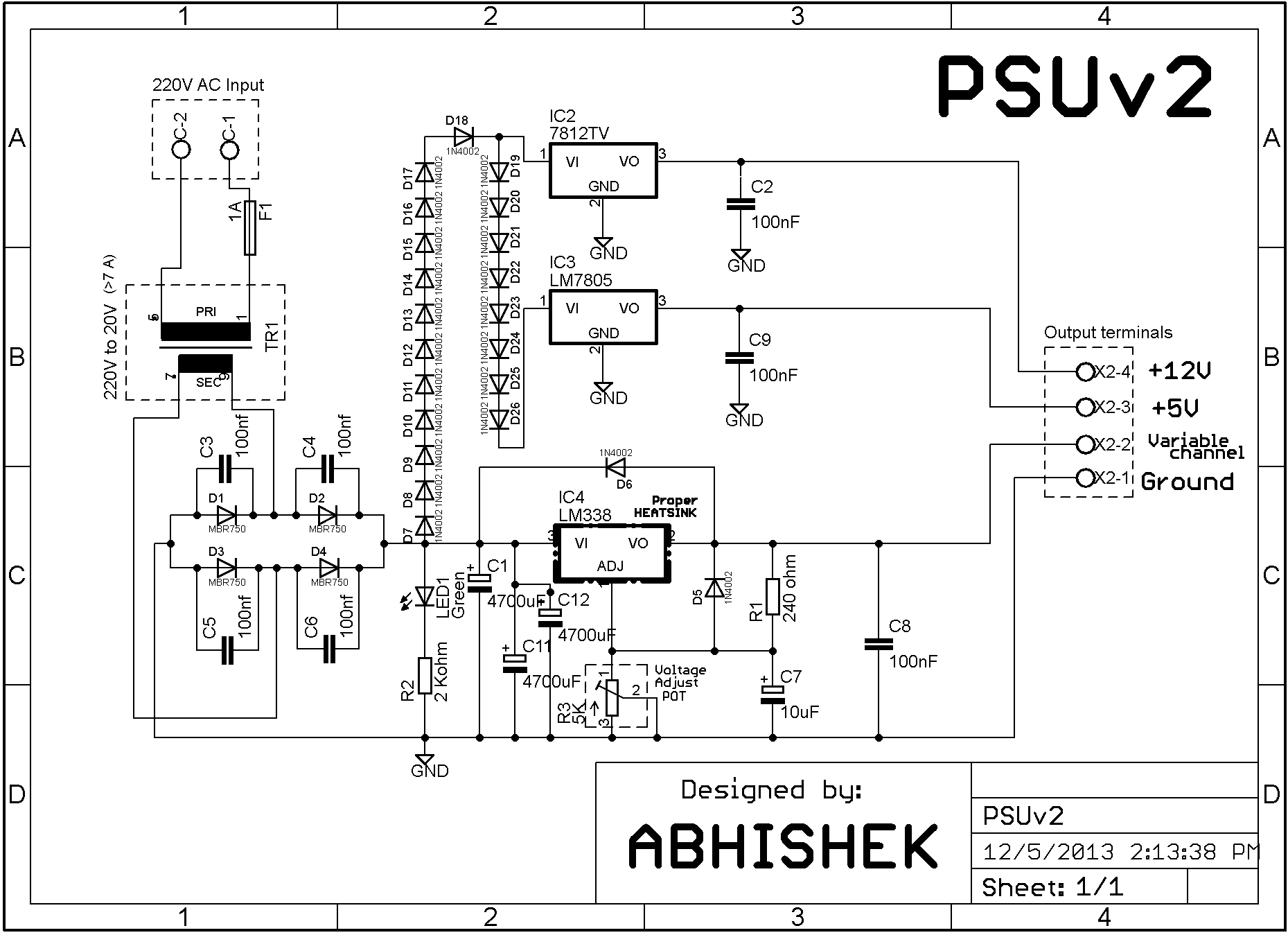
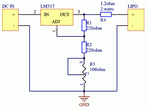
Bench PS from instructables.com LM317 charger from donutscience on the google sites link

I am using 24volts DC power supply, 7+ amps circuit is based on LM338 / 7805 / 7812 Circuit is working although few things that I'm not sure off.

I've faced few issues:

First, when running low voltage, too much heat will be generated, what's the best method to reduce voltage before the voltage regulator? The schematic I linked shows 18+ diodes in a row each diode reducing .7 volts, the author and logic says this is not a good idea, Zener diode would consume too much wattage I guess,(it would be in parallel no?) voltage divider is a good proposal but I'm not too sure, if someone can kindly point me out.

Secondly, let's say I'm charging a lipo battery, limiting current will be using a current limiting resistor (1 ohm 10 watts for example), but won't that reduce the voltage? was thinking of a high wattage potentiometer (10 ohms, to make it a variable voltage variable current Bench Power Supply) but something doesn't seem right there, I've tried simulating the circuit using LTspice but output current is off by a lot.

\$\endgroup\$
5
  • 5
    \$\begingroup\$ Well, your first mistake is trusting anything on Instructables. \$\endgroup\$
    – Majenko
    Commented Mar 14, 2015 at 23:04
  • 1
    \$\begingroup\$ "the author and logic says this is not a good idea" and then you want to build it? why? \$\endgroup\$
    – PlasmaHH
    Commented Mar 14, 2015 at 23:07
  • \$\begingroup\$ Never use a voltage divider for a power-supply. These are good only for high-impedance loads such as logic inputs. \$\endgroup\$
    – DoxyLover
    Commented Mar 14, 2015 at 23:28
  • \$\begingroup\$ Is putting 10+ diodes in series really a thing? I mean, will I ever need it for real? \$\endgroup\$ Commented Mar 14, 2015 at 23:52
  • \$\begingroup\$ This circuit WILL destroy LiPo or LiIon batteries. For LiPo/LiIon use a proper charger IC (available and cheap) or a circuit DESIGNED to meet the needs. \$\endgroup\$
    – Russell McMahon
    Commented Mar 28, 2015 at 4:50

2 Answers 2

1
\$\begingroup\$

1) The best way to reduce heat, assuming you insist on a linear regulator, is to use separate secondary windings to produce the raw voltages on your regulators. 20 VAC is OK for 25 volts, but 12 - 15 VAC for the 12 volt supply and 6-8 VAC for the 5 volt supply is much better. Of course, then you need separate rectifiers and raw DC capacitors, too.

2) If you must use the existing transformer, zeners are (technically) an excellent choice. The 1N3998A is available from Digikey, and you can use one for the 12 volt supply and 2 in series for the 5 volt supply. As long as output current is less than 1.5 amps you'll be fine. Of course, you'll need heat sinks for them, since each will dissipate 6 watts per amp. Of course, you may not be happy with the $25 price tag. That's per zener.

Power resistors are certainly possible, and about 10 ohms and 20 ohms will work. (They cannot be in series as the diodes are in your schematic). They'll need to be at least 10 watts and 20 watts for the two values I've given, and more is better. They'll also need cooling.

The problem with any linear regulator is that raw DC current must equal output current, and that current times the voltage drop from raw to final voltage is the amount of heat that must be dissipated in the supply.

3) In the charge circuit, it's true that the resistor will drop some voltage, but in direct proportion to current being drawn. So, as the battery charges, its voltage will rise, and the charge current will drop. At the very end of the charge, the battery voltage will essentially equal the charge voltage, the current will be very small, so the resistor drop will also be small. In fact, it is the difference in voltages divided by the resistance which determines what the current will be.

\$\endgroup\$
1
  • \$\begingroup\$ thank you, your answer and Majenko's sums it up, highly appreciated \$\endgroup\$
    – Ele
    Commented Mar 14, 2015 at 23:37
1
\$\begingroup\$

A proper variable power supply will employ multiple taps from the transformer. As you reduce your output voltage below each tap's threshold it will switch to the next lowest tap to keep the power dissipation at a minimum. The more taps you can afford on your transformer the more efficient it will be.

Using linear voltage regulators to reduce a large voltage to a small voltage (24V+ to 5V) is idiotic unless you're only going to be drawing minuscule currents. The heat produced will be unmanageable.

Far better is to first reduce the voltage through a very efficient means, such as through a switching regulator. If you don't need the smoothness of voltage that a linear regulator gives you then you can even do away with the (somewhat aged and ropey by today's standards) 78xx regulators and just use 5V and 12V switching regulators.

You can even use an adjustable switching regulator for the variable voltage output if you don't need it to be low ripple, or use a range of switching regulators to provide a range of voltages which you would use like the taps of the transformer to keep the input to the adjustable linear regulator as small as possible. A microcontroller could be used to decide which input voltage should be used at any one time and switch to it as needed.

As for constant current... You can have constant current or constant voltage, but having both is not really possible. You can have constant voltage and limited current, but one of them has to be variable.

For an LM317 constant current supply the current set resistor goes between the OUT and the ADJ, and you take the output from the ADJ pin. There is no resistance to ground.

\$\endgroup\$
0

Your Answer

By clicking “Post Your Answer”, you agree to our terms of service and acknowledge you have read our privacy policy.

Not the answer you're looking for? Browse other questions tagged or ask your own question.