0
\$\begingroup\$

I built a circuit that uses the 74LS163 synchronous counter. I am using in such a way that I reset the counter, using the /clear input pin, externally via and LPF connected to a tactile switch.

The design works fine, except that I am getting a strange output voltage from the clear pin. A block diagram presented in the datasheet for this pin is:
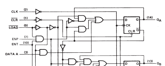
enter image description here

So, clearly the clear pin is an input to a gate, so how could a constant voltage appear at this terminal? Specifically, I am observing a ~1.41V on this terminal when it is left floating, and 1.11V when connected to the LPF with the switch fully depressed. I thought perhaps there was some excess charge at the transistor base, so I directly tied the clear pin to ground to discharge it. Upon removing this pin from ground the ~1.41V returned immediately.

The schematic I have wired is as follows: enter image description here
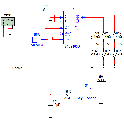
When the switch is fully depressed, the capacitor will only discharge down to 1.11V. If I disconnect the clear pin from the capacitor anode then the capacitor will fully discharge to 0V as expected, so something is going on here that I cannot explain. I tried replacing the '163 with different physical device to rule out a malfunctioning chip, but the device I replaced it with also exhibited this behavior.

\$\endgroup\$

2 Answers 2

1
\$\begingroup\$

This behavior is both correct and expected. The input stage of a TTL device acts as a current source, so some voltage will always be present except on a short to ground.

R12 should tie the input to Vcc, and there should be no (or at least a much smaller) resistance in series with the swtich.

\$\endgroup\$
13
  • \$\begingroup\$ Ah, I see. So since the input is being driven LOW the junctions are forward biased and as such are conducting current to ground (or through 25k to ground in my case) and therefore is not allowing sufficiently low voltage to reset the circuit. Would this only be true for NPN input stages like was shown in your linked question? Also, is it frequent that only a junction of a transistor is used, as opposed to the entire device, as was also shown at the link? It seems like a clever idea really, to drive Q2 with the base-collector junction current when the base-emitter is reverse biased. \$\endgroup\$
    – sherrellbc
    Commented Mar 17, 2015 at 18:43
  • \$\begingroup\$ Would it not be true also, however, that even when the base-emitter junctions are forward biased that current will flow through the base-collector junction? There is nothing setting the collector voltage (of Q1) to reverse bias it, at least as far as I can tell. That said, it seems like both junctions would be forward biased in this case and the device would be in active mode. \$\endgroup\$
    – sherrellbc
    Commented Mar 17, 2015 at 18:43
  • \$\begingroup\$ The voltage drop beyond the B-C junction is 1.4V, which is what you measured at the input. If the voltage drop is lower after the B-E junction then the B-C junction will not be forward biased. \$\endgroup\$ Commented Mar 17, 2015 at 18:43
  • 1
    \$\begingroup\$ If you look at the circuit in the linked question, both Q2 and Q4 each have a 0.7V drop after the collector, since each present a B-E junction after Q1. Since Q4's emitter is grounded, the voltage at Q1's collector is 1.4V. And since both of Q1's junctions have the same drop, the voltage at the emitter must also be 1.4V. \$\endgroup\$ Commented Mar 17, 2015 at 18:59
  • 1
    \$\begingroup\$ Measuring the voltage with a DMM will result in the diode conducting. It would be on the order of microamps, but that is enough. \$\endgroup\$ Commented Mar 17, 2015 at 19:16
2
\$\begingroup\$

Inputs of bipolar TTL (74xx, 74LSxx, and others without a "C" in the middle) parts source current, so require a fairly low resistance to ground to be recognized as a low.

You may need to draw up to 0.8 mA from the Clear input pin (and most others) to get the pin below 0.4 volts, so it will recognized as a Low.

CMOS versions (74 AC, 74HC, etc) have very high impedance inputs, and should work with your Clear circuit, if you add a 100K pull-up resistor, although I'd use a 10 K pull-up, and reduce R12 to 1K or so.

\$\endgroup\$
2
  • \$\begingroup\$ Very easy fix, and reading some of this info I think it should work. \$\endgroup\$
    – sherrellbc
    Commented Mar 17, 2015 at 18:34
  • \$\begingroup\$ I just tried the 10k/1k suggestion and measured 650mV at the /clear terminal. I changed the 10k to 100k and actually measured 3.4V! I removed the pull-up resistor completely and measured 250mV .. Any help with the logic here? To me is seems the pull-up value would have no impact on voltage since the impedance to ground is 1k either way! I am thoroughly confused. \$\endgroup\$
    – sherrellbc
    Commented Mar 17, 2015 at 23:17

Your Answer

By clicking “Post Your Answer”, you agree to our terms of service and acknowledge you have read our privacy policy.

Not the answer you're looking for? Browse other questions tagged or ask your own question.