I would like to use a LiIon cell recovered from an old laptop to power my bike light (a bulb one, 2.4W 6V).
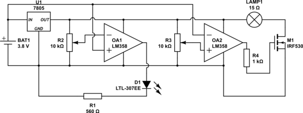
I thought about using an opamp controlling a MOSFET to avoid overdischarge (MOSFET ON for Vbatt>3.1V), and also an opamp to signal when the battery is almost drained (LED ON for Vbatt<3.2-3.3V).
As DC-DC step-up I used a small board meant to be used for phone chargers and I measured an output of 4.8V with the load connected. It is way lower than the nominal 6V of the light bulb, but this is a minor issue, since I can easily swap that circuit with another one.
The circuit is (of course the LM7805 is a placeholder for the step-up board and also my MOSFET is different: a BUK556-60A I had lying around):

simulate this circuit – Schematic created using CircuitLab
My problem is that the LM358 (or the TL081 I have at home) is not rail to rail and apparently its output cannot put the MOSFET in saturation. For example, I measured on the breadboard the following values: 3.48V Vbatt, 3.17V threshold for the comparator OA2 (it was not 3.1V as I wrote above) and 3.9V on the gate of the MOSFET (and on the output of the opamp) resulting on a drop along the MOSFET of 0.8V.
How can I prevent overdischarge of the LiIon battery without losing almost 1V on the switch I have to place inevitably somewhere? A NPN transistor would not change the situation much, I think.
Update
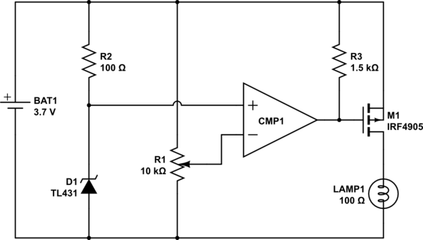
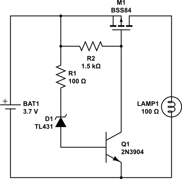
This circuit technically doesn't prevent the batteries to drain, but it will light up the LED when charge is low and will stop the bike like altogether when the battery is almost empty, resulting in me being forced to charge the batteries.
I didn't show in the circuit the physical switch I plan to use to disconnect the batteries completely when no light is needed.


