3
\$\begingroup\$

I'm having a bit of an issue with a circuit I've built, and I'm hoping someone could provide some input. I'm making a stepper driver based on the A4983, and am having an odd issue - made even more odd by an accidental discovery. Namely, the driver only produces current to the motor when one of the outputs (either 1A or 1B) are connected to GND with a low-value resistor.

How I came about this discovery was by accident - my DMM was left in current measuring mode and the motor would miraculously start spinning when I connected from GND to either 1A or 1B. (I intended to measure voltage on the output, which sits around 7V when measured at 1A.)

My bench top PSU reflects the same, showing a nominal 10mA draw for the entire circuit (including uC and a few other components), until this happens, and then it shoots up to 160mA when doing this. Hooking the DMM up where output 1A is fed through the DMM common, and from DMM measure line to motor pole results in no current measured.

My circuit is below, can anyone see any obvious mistakes? I'm completely stumped, connectivity tests on the circuit seem to indicate that everything is connected as expected. All other components are working properly, and AEN and other inputs are set as expected (verified and measured). The motor also performs properly when attached to another driver.
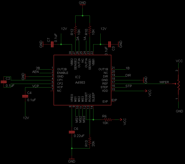
schematic

\$\endgroup\$
3
  • \$\begingroup\$ There's your schematic (We want useful images like that, but need to limit new users for spam reasons). I didn't create the tag, we don't want tags for all ICs. [stepper-motor-driver] would probably be the lowest we'd want to go. \$\endgroup\$ Commented Jun 28, 2011 at 2:32
  • \$\begingroup\$ A cursory look at your schematic reveals nothing obvious to me, but I rarely work with motors. Hopefully someone else can help you with your problem! \$\endgroup\$ Commented Jun 28, 2011 at 2:33
  • \$\begingroup\$ @kevin - totally understand on the images issue. Thanks for the advice on tagging as well, I will make sure to follow it for future posts! \$\endgroup\$
    – indrone
    Commented Jun 29, 2011 at 0:13

2 Answers 2

3
\$\begingroup\$

Your shunt resistors R10 and R12 appear to be way too big. Therefore the device is always in current-limit.

Read pages 7 and 8 of the datasheet, use Ohm's law as suggested. Also make sure to calculate the power rating on the sense resistors.

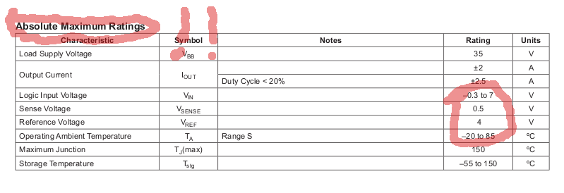
Also, pay attention to voltages on the SENSEx and REF pins: enter image description here

\$\endgroup\$
2
  • \$\begingroup\$ You are completely right. I must've put those values in there when working on it initially, expecting to fill them in later (since they are appropriate value for the adj. pot.) and never went back, nor verified before I assembled the board. They should be MUCH lower. I also completely missed the needed resistor before the pot. to reduce the voltage going into VRef. Thank you so much! \$\endgroup\$
    – indrone
    Commented Jun 28, 2011 at 3:37
  • 1
    \$\begingroup\$ It's worth noting that Absolute Maximum Ratings are exactly that: Absolute Maximum. The device should never operate at these levels. Elsewhere in datasheets you will find values for normal operation, and they're always lower. \$\endgroup\$
    – stevenvh
    Commented Jun 28, 2011 at 6:32
2
\$\begingroup\$

To expand on @markrages comment:

If you want a motor current of 1A (and derating the voltage across the sense resistor to 0.2 at the desired target current, since a voltage of 0.5V is the maximum rated input at the sense pins), your sense resistors need to be:

$$ V = I*R $$ $$ 0.2V = 1\Omega*R $$ $$ \frac{0.2V}{1\Omega} = R $$ $$ 0.2\Omega $$

With 10K resistors, your total motor current is 50 uA, so the motor is not doing anything.

Furthermore, the allegro motor drivers need special non-inductive resistors. The common wire-wound (white brick) power resistors will produce strange behavior. Ohmite produce a nice non-inductive power resistor I have used before here.


The A4983 motor driver uses a "chopper" current limiting system.

  • Initially, the IC applies the full supply voltage across the stepper motor.
  • Since the motor is inductive, the current through the motor increases gradually.
  • The driver IC compares the reference (ref pin) voltage to the voltage across the sense resistor multiplied by a gain of 8.
    $$ I_{Trip}MAX = \frac{VREF}{( 8 * RS)} $$
  • When the sense voltage (times 8) exceeds the reference voltage, the driver shorts out the motor coil. However, again, since the motor is inductive, the current through the motor dies not immediately stop, but it decays gradually over time.
  • The current decays for a fixed period of time (Toff in the datasheet), it then applies full power across the motor again, and the cycle repeats.

So you see, the sense resistor is absolutely integral to the system working properly.
Furthermore, the whole affair effectively forms a simple DC-DC converter, with the motor functioning both as the inductor and load.

Microstepping is accomplished by simply dividing the reference voltage down inside the IC using a 4 bit DAC before comparing it to the sense voltage.


The only other comment I have is that it would probably be a good idea to place a 0.1uF cap between the ref input and ground.

\$\endgroup\$
2
  • \$\begingroup\$ Thank you very much for the detailed explanation, it is definitely clearer when condensed like this, than it can be in some parts of the datasheet. \$\endgroup\$
    – indrone
    Commented Jun 28, 2011 at 13:03
  • \$\begingroup\$ Hah, no problem. I recently completed a project involving a networked control system for ~250 (!) stepper motors based around Allegro drivers, so I have become rather familiar with how they work. \$\endgroup\$ Commented Jun 28, 2011 at 22:53

Your Answer

By clicking “Post Your Answer”, you agree to our terms of service and acknowledge you have read our privacy policy.

Not the answer you're looking for? Browse other questions tagged or ask your own question.