5
\$\begingroup\$

What is the mechanism by which Triodes in audio tube amps generate harmonic distortion?

It is my understanding that the distortion is generated by means of electron bunching. That is, when the grid voltage swings negative and is larger than the cathode voltage, it blocks off electron flow from the cathode to the anode plate and creates a cloud of electrons with non-uniform density. When the negative grid voltage falls to 0, this cloud of electrons moves forward to the anode in the form of a bunched wave which adds harmonics to the signal. Or when there is a capacitor connected to the anode lead by means of a T-junction that can cause the anode voltage to swing negative, repelling the oncoming free electrons emitted by the cathode and creating a "space charge" between the anode and the grid with nonuniform density due to velocity modulation. Is this correct? If not please explain why.

\$\endgroup\$
1
  • \$\begingroup\$ Are you referring to some publication or is this your own thoughts? \$\endgroup\$
    – Andy aka
    Commented Mar 26, 2015 at 19:30

3 Answers 3

8
\$\begingroup\$

All the effects you mention are much faster than relevant to audio signals, so have nothing to do with audio distortion.

The dynamic characteristic of a triode makes it look sortof like a variable resistor with a variable voltage offset once you get to some minimum current level. Both these are controlled by the grid voltage. However, this is merely a first order approximation of what really happens. The exact relationship from grid voltage to plate voltage with a fixed plate power supply and load resistor is non-linear. You get more output change for the same grid voltage delta at high grid voltages than low ones near "cut off".

This non-linear function causes harmonics if not dealt with. The usual way of dealing with this is to operate the tube over a part of its range where the relaltionship is not too non-linear, and to use negative feedback. Usually you'd use a cathode resistor for some immediate negative feedback around a single stage, then some global negative feedback around most of the amplifier.

These techniques are effective enough in a well-designed tube amp to not be much of a issue. The speaker will introduce considerably more distortion. The main difference between tube and transistor amps is what happens when you overdrive them. Tubes are more "soft" in getting to their maximum values. The tops of too-large waveforms are not just hard clipped at some level, but "squashed" before being eventually limited. This type of distortion is more pleasing to many people, especially if it's done symmetrically on the tops and bottoms of the waveforms.

\$\endgroup\$
4
  • \$\begingroup\$ Excellent answer! This is exactly what I was looking for. \$\endgroup\$
    – Mr X
    Commented Mar 26, 2015 at 21:39
  • 2
    \$\begingroup\$ Symmetrical circuits are good when it is desired to eliminate distortion, as they (theoretically) completely eliminate even harmonics. Where distortion is deliberately added, as in guitar amplifiers, asymmetric circuits / even harmonics can be very desirable, depending on taste. Even harmonics correspond to octaves. instructables.com/id/… sums it up, though I don't know why he's adding a diode clipping network to a valve amp. As he says, an asymmetric (say 2 forward, 1 reverse) diode network gives the most "tube like" sound. \$\endgroup\$ Commented Mar 26, 2015 at 23:37
  • \$\begingroup\$ @steveverrill Power-of-2 harmonics correspond to octaves. The other even ones correspond to tenths, twelfths, ... The notion that all even-order harmonics are consonant is an engineering myth. \$\endgroup\$
    – user207421
    Commented May 30, 2015 at 20:03
  • \$\begingroup\$ @EJP the interval known as a tenth in music is either a minor tenth, 12+3=15 semitones (2.3784:1 eventempered or 12:5 just) or a major tenth 12+4=16 semitones (2.51984:1 eventempered or 5:2 just.) These are not harmonics The interval known as a twelfth in music is 19 semitones (2.997:1 eventempered or 3:1 just, the 3rd harmonic.) The 6th, 10th and 12th harmonics would be known musically as a 19th, major 24th and 26th respectively. As I said, circuits with both symmetric and asymmetric characteristics are used and it's a matter of taste. Anyway, the 10th and 12th harmonics will be quite weak. \$\endgroup\$ Commented Jun 1, 2015 at 12:13
1
\$\begingroup\$

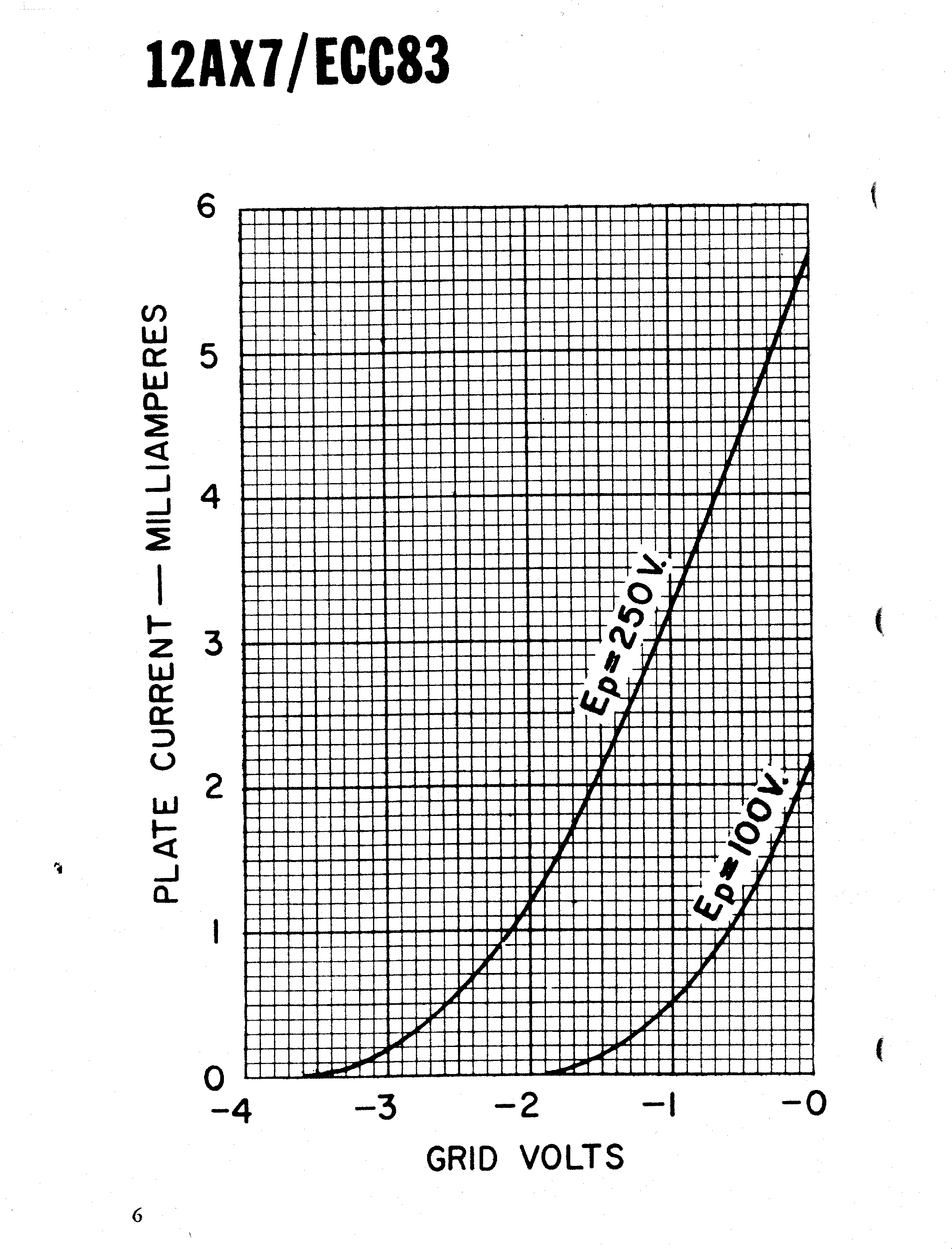
When you're talking electron bunches and stuff, that's device physics, and it happens on a timescale much faster than audio signals. (Generally you have to get up to microwave frequencies to make use of collective electron effects.) However you are right that it does matter; the device physics explains why the 'macroscopic' transfer function of a given device is shaped how it is: 12AX7 curves via Duncan Amps

It's the linearity (or nonlinearity) of these curves that determines the distortion of the amplified signal. You can see that when you put in a sine wave on the grid, as long as the line is perfectly straight, you'll get a scaled copy of the input waveform in plate current. Any deviation from perfect straightness means you will get distortion. The typical way to analyze this (on paper) is with Volterra series methods.

\$\endgroup\$
1
0
\$\begingroup\$

The anode current in a vacuum tube has a power law function relative to the voltage at the grid. This gives harmonic distortion.

This link gives a good description.

How Vacuum Tubes really work

\$\endgroup\$

Your Answer

By clicking “Post Your Answer”, you agree to our terms of service and acknowledge you have read our privacy policy.

Not the answer you're looking for? Browse other questions tagged or ask your own question.