1
\$\begingroup\$

circuit

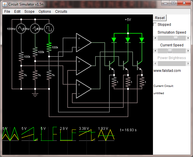
In this here circuit the function generators at the left represent the digital output pins from a microcontroller. I happen to be using an Arduino Uno for that purpose at the moment and the relevant component would be the ATmega328 of course.

Now I am having a few issues with this circuit. One seems to be that the MCU pins don't quite provide the output voltage range I expected them to. Even when setting PWM duty cycle to 100% one of the pins only goes up to 4.1V (measured with a multimeter) while the others go to about 4.5-4.6V. Similarly at PWM 0% duty cycle they do not quite drop down to 0, I'm getting 0.28V on one of them. My calculations are based on these being at 5V so the resulting current is not accurate.

My rail-to-rail opamps (MCP6004) work well but not at the bottom range. I have the Vss hooked up to ground but when V+ is reconnected to ground, the Vout hovers at a slightly positive voltage. I'm reading Vout's of 0.8V, 0.2V, and 0.65V from this particular setup. I imagine that this might be fixed if I can provide a negative Vss but I thought these opamps are supposed to be rail to rail! I understand that there may be physical limitations in implementing these devices however, and I may just have to live with it.

As a result of all these factors, my LEDs do not switch off when the input pins are set to zero (and the MCU doesn't even reach zero, and even when wiring V+ to zero, Vout doesnt reach it) and the precision of current control during the on-portion of the duty cycle is still dependent on the MCU output voltage, which does vary.

My original purpose of adding opamps to the circuit was to allow me to control the emitter voltage at the transistors via the opamps, which gives me analog current regulation capability as well as improved efficiency by allowing me to lower the current sensing resistor value. However it seems that certain limitations (mostly coming form the opamp) have resulted in suboptimal performance.

My previous working iteration of this circuit was simpler. It had no op-amps, and was simply driving the transistors' base with the MCU out. This proved to be functional because during the PWM-off portion at 0.3V or so it wasn't enough to switch the transistor on, and zero current flowed through the diode. During PWM-on, the emitter voltage became Vin-Vbe (Vin = MCU output pin voltage). The downside of this is that my current regulation resistor could not be reduced significantly. Suppose Vbe is 0.7V and I have Vin = 1V (via voltage divider on MCU out). Then V_emitter is 0.3V during the on-cycle and setting the current would be difficult.

What I can do now is to abandon analog current control altogether, and try to get as efficient and small (in terms of component count and size) as possible. From what little I know about MOSFETs it seems like they are the way to go for doing power switching. I don't know if I'll need a pulldown resistor (is that even the correct term?) on the Gate or not since it will no longer have a path to ground like the base-emitter junction provides. One thing I am wondering is how I can make things efficient when I am trying to drive 3 LED's which have forward voltages differing by up to 1.5V. Suppose at my target current, the red LED's Vf is 2.4V and the green LED's Vf is 3.7V. In any reasonably simple circuit that powers both of them, running off of a 5V power rail, almost half of the power used for the red LED must be dissipated as heat?

It may turn out that specialized LED driver IC's will be the most suitable choice for a PWM application. I will need to experiment with my TL4242's I've got. They are sufficiently tiny for me to do amazing things but I actually can't even test them till I get my supplies to build some PCB's. That surface mount package is TINY.

Another thing I can try is moving to a higher voltage power source and putting the MCU ground at a higher potential so that I can give my opamps a better range. I'm not really sure how I can do this while maintaining good efficiency however. Are there any circuits or IC's which can somehow provide me with a negative potential with just receiving a positive potential? Or will that violate the conservation of charge or something like that?

Though this project I have arrived at an appreciation of just how difficult it is to design functional, small, and efficient circuits. I'd like to thank in particular users stevenvh and Olin Lathrop as they have been consistently helpful in pointing me in the right direction.

\$\endgroup\$
1
  • \$\begingroup\$ is the output mode of the lower-voltage output pin set to bipolar? Or is it open collector resistor-to-high? \$\endgroup\$
    – Toybuilder
    Commented Jun 29, 2011 at 23:52

4 Answers 4

2
\$\begingroup\$

There are various misconceptions here.

The emitter resistor value has no effect on efficiency. All the current for each LED is coming from the 5V supply. Whatever part of that voltage the LED doesn't use times the current is going to be wasted as heat. Small emitter resistors only more the dissipation to the transistors. The total dissipation is the same.

I thought I mentioned it in your other question, but the emitter resistors should be a larger value. At 1 Ohm just 1 1mV offset will cause 1mA thru the LED, which is probably dim but visible. From your voltage divider ratio and the 1 Ohm emitter resistors, it looks like you're aiming at a bit over 300mA LED current. Didn't I go thru a detailed calculation of the emitter resistor value in your other question?

I don't know what kind of LEDs these are, but most likely you can afford at least a volt accross the emitter resistor, so 3.3 Ohms would be a better choice that will give you more control.

As for the not quite 0 and 5 volt output, that's probably something the Arduino is doing. Keep in mind that arduinos are Simplified for the masses. It wouldn't surprise me if there is a resistor in series with each output as protection.

The opamps are probably working fine enough. Every opamp has some offset error, and if these are a little positive, their outputs will go high just enough to turn the transistors on a little to make that offset voltage appear accross the emitter resistor. This is yet another reason for using a larger emitter resistor.

\$\endgroup\$
2
  • \$\begingroup\$ @ Olin : You said The emitter resistor value has no effect on efficiency. All the current for each LED is coming from the 5V supply. But he can increase the efficiency by decreasing the supply voltage while reducing the emitter resistance, so that the led current is not reduced, right? Will that have an adverse effect? \$\endgroup\$
    – Aqua
    Commented Aug 18, 2011 at 8:47
  • \$\begingroup\$ @aqua, Yes, if you reduce supply voltage without affecting LED current you are improving efficiency. The user seems to believe that reducing his resistor in series affects efficiency. S/He is not adjusting voltage. \$\endgroup\$
    – Kortuk
    Commented Aug 19, 2011 at 15:35
0
\$\begingroup\$
  1. You initial idea uC->transistors is the best way to go. You won't improve anything with any additional stuff to drive your transistors. Switching to MOSFETs does not solve anything here.

  2. You surely can get negative voltage out of positive - look for inverting DCDC converter chips.

  3. If you are thinking about power efficiency: You need to have separate DCDC just for the leds, which have output voltage = slightly over voltage needed for LEDs at fullpower with tiny resistor, then use P-MOSFET transistors with 100Ohm gate resistor to drive these leds from your uC with PWM. This way you will have nearly 0 energy looses. As you have 3 different LED's - you will need separate DCDC for each of them. That would be really complicated :-)

  4. I don't see what benefits you can get with specialized LED drivers... TL4242 is just linear regulator, I don't see much benefit comparing to what you have now...

\$\endgroup\$
0
\$\begingroup\$

You write that you want to control several leds of different Vf and you want to do this in a power-efficient way (consider why?). These are some solutions ranged from most power efficient to least and some of the pros/cons:

Most efficient solution: a switching DC/DC regulator for each LED-type will produce the driving current needed. There are chips that do exactly this for many channels. For example the 3-channel LT3492. You apply your external PWM to its three channels. These chips are designed for exactly this purpose, so they are probably cheaper than having 3 separate ordinary DC/DC converters. I would use this for the 100 mA and upwards range, or something, since normally you don't want to dissipate all that residual heat from the linear regulation.

Next best: the next best thing is actually to PWM the LEDs themselves just like you tried first, but you can't drive them directly from the Arduino. Like Barsmonster wrote, drive an N-FET from the Arduino through a small gate resistor and put a current-control resistor in series with the LED and use a VCC_LED which is just higher than the highest Vf you'll need. Since you will run at a constant DC, you will waste some power in the resistors corresponding to the LEDs with lesser Vf.

Next next best: your current circuit. The extra BJT (transistor) will waste some more power (in the case of dimming and you try to have a well matched VCC_LED). I would use this circuit if dimming the LED by PWM is impossible (for example if you can't PWM it fast enough for your application, like data-transmission or measurements). For humans, PWM by dimming is certainly enough. You can run it yourself like you did, it looks like a good implementation if you can tweak the values to match your desired range, otherwise TI has a range of cheap multi-channel chips that do exactly this from a very simple serial port from the Arduino with almost no external components. Consider the 8-channel 120 mA TLC5916 for example (there is a large series depending on number of channels and driving current).

For a well-matched VCC_LED, a FET instead of a BJT in this circuit is better due to the much lower voltage-drop when switched on. For a higher VCC_LED, it doesn't matter since the FET has to absorb the drop anyway (just like the BJT + resistor, as others have commented).

Addendum: note that the Vf of LEDs as specified in the datasheets have a spread which you have to add to the margin if you match the VCC.

\$\endgroup\$
3
  • \$\begingroup\$ What Olin said about the emitter resistor also goes for the transistor: its power dissipation doesn't decrease efficiency; transistor + resistor together form the current limiting resistor you need anyway. \$\endgroup\$
    – stevenvh
    Commented Jun 30, 2011 at 8:33
  • \$\begingroup\$ @stevenvh: yes, but the BJT puts a limit on how low the effective resistance of the transistor + resistor can go, so for a decently matched vcc_led and dimmed to 50%, the PWM on/off approach is more efficient. \$\endgroup\$ Commented Jun 30, 2011 at 8:46
  • \$\begingroup\$ Sure, I agree with the PWM! I meant current limiting in the on state. \$\endgroup\$
    – stevenvh
    Commented Jun 30, 2011 at 8:48
0
\$\begingroup\$

There will be small input offset voltages in the op-amps that can cause the output to raise slightly. But since the output must pass through a base to emitter diode drop in the transistor before it reaches the negative input terminal, it is raising to 0.7V or so and turning the LED on slightly. The solution to this is to use a high value pull-up resistor from the negative input terminal to the high voltage rail. The value of this resistor should be calculated for the worst case input offset voltage. If the worse case input offset voltage is 3mV, for example, you would want to pull up the negative input terminal 4mV. This will force the LED off with a 0V input signal. You should also use a base current limiting resistor as already mentioned, but this alone won't prevent partial power on.

I'm surprised you're getting such low voltages out of your micro. You mentioned measuring the voltages with a multimeter and I'm wondering if these are DC voltages or while it was PWMing? The multimeter may not be fast enough to provide accurate readings of the PWM signal. With such a huge load (200K), they should be getting up closer to the rail. And the .28V ground sounds bad as well. This should be getting dead close to ground since the pin does not have to eat any current in this circuit. It seems like something is wrong here or the measurements are incorrect. The .28V may just be due to the current from you measurement device, but I wouldn't expect any turn-on signal at the op-amp input signal during normal operation.

\$\endgroup\$

Your Answer

By clicking “Post Your Answer”, you agree to our terms of service and acknowledge you have read our privacy policy.

Not the answer you're looking for? Browse other questions tagged or ask your own question.