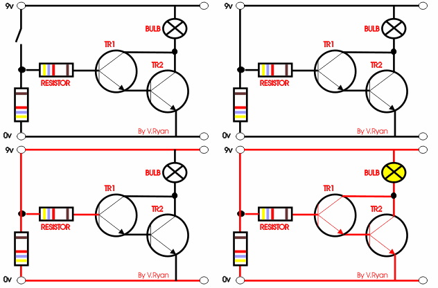
Let me know how to calculate the TR1 base resistor value in the following darlington pair
and also explain the role of pull up and pull down resistor in a circuit thank you.

-
1\$\begingroup\$ You should be able to figure this out easily. But first you need to specify which transistors you are using. \$\endgroup\$– Dwayne ReidCommented Apr 9, 2015 at 4:14
-
1\$\begingroup\$ Yellow-violet-red-brown is 4.7 kΩ ±1%. \$\endgroup\$– CL.Commented Apr 9, 2015 at 9:26
-
2\$\begingroup\$ Why don't you just use a MOSFET? \$\endgroup\$– hkBattousaiCommented Apr 9, 2015 at 9:32
-
4\$\begingroup\$ Why don't you draw a proper schematic instead of a cartoon? \$\endgroup\$– Andy akaCommented Apr 9, 2015 at 9:36
1 Answer
A bipolar transistor is a form of current amplifier. The gain is denoted as hfe on specifications and is in the order of 100. To get the gain of a darlington pair, multiply that figure for the two transistors together. Often transistors' specifications include two values for hfe: The typical and the minimum. In this case, use the minimum values from their datasheets.
Then calculate the current the load would draw. You then divide that current by the combined current gain of the two transistors. That is the minimum current that needs to go into the base of the transistor on the left.
A pull-up resistor is used to pull the voltage of one end up to that of the other end. Similarly, the opposite is true of a pull-down resistor.
In the circuit you've shown, the lower-left resistor combined with the upper left resistor act together as a pull-down resistor when the switch is open (i.e. disconnected). This makes sure the darlington pair is off; important because with the high gain it would have, EMI could basically be flipping them on and off. Also, there may be slight current going into the base via dirt on the wires and the switch, moisture and so on, which may be enough to make the bulb glow very dimly even when the switch is open.
When the switch is closed (i.e. contacts are connected) the upper-right resistor acts as the pull-up resistor.
The value needed for the lower-left resistor will depend on complicated factors such as EMI but a rule-of-thumb can be used. I would personally almost always use a 100k resistor. A higher value could be used if you are desperate to make the circuit as efficient as possible. Similarly, a lower value could be used if you find it is not turning the transistors entirely off.
The upper-right resistor's maximum value can be calculated approximately as follows:
$$R = \frac{9 - 1.4}{I \cdot h_{fe1} \cdot h_{fe2}}$$
Where I is the current the bulb draws, and 1.4v is the approximate combined voltage drop across the base-emitter junction of the two transistors. It has to supply enough current to transistor's base so they can both saturate and turn the bulb fully on.
The reason the pull-up resistor is required at all here (rather than a direct connection bypassing it) is because a transistor's base can not handle all that much current - usually no-where near as much as the collector - and because the base-emitter voltage clamps with around 0.7v across it, there would be a sort of short-circuit between the base and the positive supply and the transistor would blow. The datasheets will specify the maximum current the base can handle, but you do not need to use that in your calculations for this circuit.
