3
\$\begingroup\$

I'm building a small sensor setup that is able to measure the transmission of light through a (clouded) solution. I currently have a laser light that shines through the solution and a LDR on the other side. This works pretty well but there is quite a variation between batches of LDRs and the response is also not very linear. Therefor I started to play around with a photodiode instead of a LDR. (The output is connected to an 12bit ADC)

Currently I have VTB8440BH photodiode connected to a LTC1050 opamp. It's wired up in a current-to-voltage setup and the photodiode in photovoltaic mode as depicted in the datasheet of the opamp on page 13. The sampling frequency is very low somewhere around 1Hz. circuit
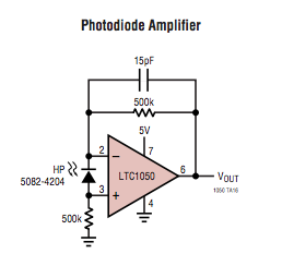
The opamp and photodiode will be placed in an environment with a pretty constant (+/- 1C) temperature of 60C. I read in the datasheet that increasing temperatures introduce increasing amounts of noise. I was wondering what the best strategy is to build this circuit, will this circuit that I showed here already be very low noise or do I need additional components to stabilise the output?

(Another small questions, what is the purpose of the 500K resistor between pin 3 (+) of the opamp and the ground? If I check the opamp calculator of Analog Devices (www.analog.com/designtools/en/photodiode/#/photoDiode) that resistor is not present)

\$\endgroup\$
1
  • 1
    \$\begingroup\$ This general type of circuit should be suitable given your low bandwidth requirements. In other cases, I suggest reading Photodiode Front Ends: The Real Story by Philip Hobbs. The very large capacitance of your chosen photodiode will presumably be reduced if you use a reverse bias of 2V. Other diodes are available with much smaller capacitance, of course. I didn't check to see whether your diode is really a good choice for low noise measurements, but the VTB8441BH has a (much) higher shunt resistance so probably will be better than the VTB8440BH. \$\endgroup\$ Commented Apr 12, 2015 at 16:44

2 Answers 2

4
\$\begingroup\$

Without knowing your illumination levels, it's impossible to tell if that will do what you need. That said, the circuit ought to work, with a couple of changes. First, eliminate the resistor from pin 3 to ground and connect directly to ground. Next, increase the 15 pF capacitor to 100 pF. Your actual photodiode has much higher capacitance than the schematic, and this needs to be reflected in the feedback cap. Worse, it interacts with the + input, and gives a big transient spike. In the original, the diode capacitance was reasonably compensated by the ICs input pin capacitance, but that's no longer true with your new photodiode. The resistor was there originally to compensate for temperature changes in the input bias current.

It's entirely possible that you have way more light coming in than this setup will handle. If so, and your output is pinned high, reduce the value of the feedback resistor. If the signal is too small, increase the resistor value, although this may also require increasing the feedback cap, which will slow the response. I don't see this as a problem, though, since you're sampling at a very low rate.

\$\endgroup\$
2
\$\begingroup\$

In a low speed case like this, you want to massively over sample and then decimate. Say thousands of samples over a period of exactly 1 second (an even number of 50 or 60 hz mains cycles). Decimate using a median filter.

\$\endgroup\$

Your Answer

By clicking “Post Your Answer”, you agree to our terms of service and acknowledge you have read our privacy policy.

Not the answer you're looking for? Browse other questions tagged or ask your own question.