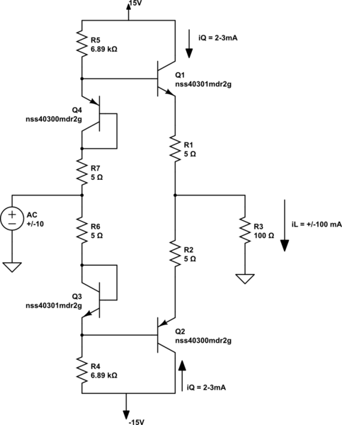
Background / Requirements:
I'm designing a typical Class AB amplifier using diode-connected BJTs to achieve the biasing. I have a requirement to keep the total quiescent current at room temperature to less than 8mA (from a single rail). Additionally the amplifier has to reliably source 100 mA \$AC_{pk}\$ to a \$100 \Omega\$ load over the industrial temperature range of \$-40^\circ C\$ to \$+85^\circ C \$. Here is the current rendition of my schematic:

simulate this circuit – Schematic created using CircuitLab
My Problem:
The resistors R4 and R5 have to be sized such that they can supply the maximum base current required by Q1 and Q2. However, I cannot have R4 and R5 too low due to my low quiescent current requirement.
I don't know how much the base current on the BJTs can vary. Before you step in and give the usual answer--"a lot" (which may very well be the case), let's look at what I have so far. I'm using the On Semi NSS40302PDR2G complementary NPN/PNP. Let's just consider the NPN case for now:
The TYPICAL \$\beta\$ is 350 and the MINIMUM \$\beta\$ is 200, both specified at room temperature and \$iC=500 \$ mA. Based on this information, what would I expect the MINIMUM beta to be at \$-40^\circ C\$?
Based on the temperature-dependence formula SPICE uses:
$$\beta(T_1) = \beta(T_0) \left[ \frac{T_1}{T_0} \right]^{XTB}$$
Where XTB can be obtained from the SPICE model (for the NPN transistor, XTB = 0.437188). We can calculate the expected MINIMUM \$\beta\$ at \$-40^\circ C\$ and \$i_C=500\$ mA:
$$\beta(-40^\circ C)_{min} = 200 \left[ \frac{273.15 - 40}{300} \right]^{0.437188} = 179$$
I can live with a worst-case \$\beta\$ of 179. Now, \$\beta\$is obviously not the only parameter to vary in a BJT. Let's look at Is and NF. From the datasheet we see that \$v_{be(on)}\$ at 100 mA is typically 0.65V but has a maximum of 0.75V at room temperature. Let's see how the collector current changes with Is and NF (the non-ideality factor)
$$i_c = I_s \left( e^{v_{be(on)}/(V_T N_F)} - 1 \right) - I_s$$
Now, solving for Vbe(on):
$$v_{be(on)} = N_F V_T \ln \left( \frac{-i_c - 2 I_s}{I_s} \right)$$
Now, let's make \$N_F\$ and \$I_S\$ be variable by some tolerance, TOL (in %):
$$v_{be(on)} = N_F(1 + TOL/100) V_T \ln \left( \frac{-i_c - 2 I_s (1+TOL/100)}{I_s (1+TOL/100)} \right)$$
Setting tolerance to zero and plugging in the 100 mA for \$i_C\$ and the remaining parameters pulled from the SPICE model gives a \$v_{be(on)} = 0.655\$ (close enough to the datasheet that I believe it).
Now how much TOL do we need to reach the 0.75V stated as the MAXIMUM in the dataseet? Solving with mathematica gives:
$$TOL \rightarrow 15.3171$$
That is, both Is and NF can vary by 15% according to the datasheet. Now we get the the Monte Carlo analysis. In order to show that my circuit above works over device variation and temperature, I am performing Monte Carlo analysis in LTSPICE by varying all the BJT device parameters by 15% and Beta by 75%. This gives me huge base currents for some cases (much more than anticipated by the \$\beta = 179\$ calculation).
Am I being too hard on myself? By varying the device parameters by 15% over temperature, some cases give me a Beta <20. Which for most BJTs would be expected, but I specifically chose the On Semi NSS40302PDR2G for the seemingly excellent Beta.
Hopefully answerable Questions:
- Is my 15% device parameter variation using monte carlo analysis too harsh? Is the \$\beta=179\$ calculation at all likely?
- If answer to (1) is "No, you will actually see \$\beta < 20\$ after building many circuits", then any ideas on how to modify this circuit to make it more beta independent without adding many (if any) components?
