2
\$\begingroup\$

I have two questions about my circuit, drving DC Motor with H Bridge. The picture below shows my design and how I drive it with signals. enter image description here

enter image description here

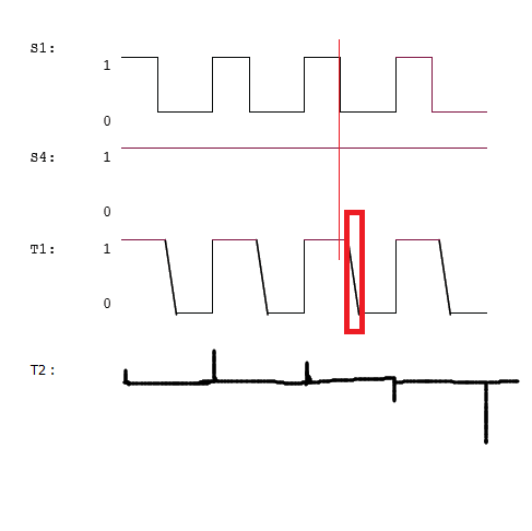
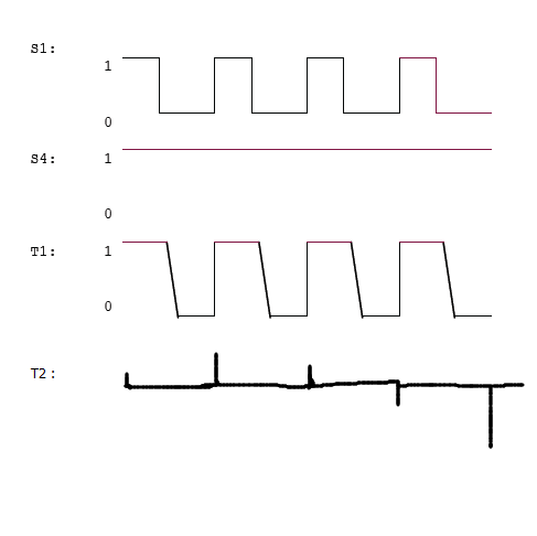
For example, when I make the motor rotate forward, I give 'S1' PWM signal and give 'S4' always 1. Then I find a problem that the signal 'T1' shows like the picture up, which means the H bridge turns off two slow!(Which will cause problem when I want to make the motor move slowly). I have change the value of R1 and R2 so as to make U1B and U2B turn off as quick as possible, but it doesn't change much for the signal of 'T1'. Then I analysis the induction electromotive force. Maybe like the picture below, enter image description here

So could you give me some advice to improve the signal of 'T1' so as to make the H Bridge turn off quickly.

Moreover, I have another problem with current monitor and I have drawn the similar signal of 'T2' in the picture 2(Sometimes it has positive burr voltage, sometimes it has negative burr voltage, like a discontinuous sinusoidal). Any advice about improve my current monitor circuit?(I add comparator after 'T2', but I want to improve the signal of 'T2'). Thanks for your suggestion!

Here is one more picture to descrbe my problem. I want to make the time of red rectangle short.enter image description here

\$\endgroup\$

2 Answers 2

2
\$\begingroup\$

To switch a power MOSFET, you have to move a substantial charge through the gate and the source. The datasheet will specify something like "total gate charge". In order to move all that charge in a short time, you need high current. And in your circuit you can't have high current, since the current through the gate is ultimately limited by R1 and R3.

In other words, the problem is that with your design, U1B does not fully turn off until some time after S1 goes low. And when it does turn off, it does so slowly, which is why you see the voltage at T1 ramp down slowly. See What is MOSFET gate drive capability and why do I care about it?

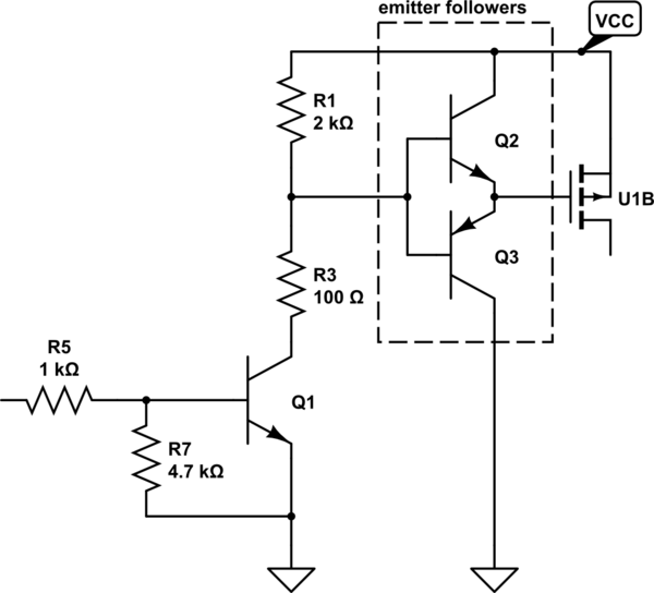
In order to reduce this problem, you need to increase the current that your gate driver can source and sink. A simplistic solution is to add a pair of emitter-followers, like this:

schematic

simulate this circuit – Schematic created using CircuitLab

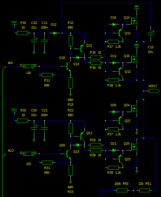
You can get fancier with a discrete approach like the one that follows. In addition to having emitter followers to increase the current drive, it uses a clamp (D13, D23) to reduce the storage delay of the BJTs Q11 and Q21. You can read more about it in another answer.

half-bridge

Or, you can just buy an integrated MOSFET gate driver and call it a day.

\$\endgroup\$
8
  • \$\begingroup\$ Thanks for your suggestion, the push-pull driver for MOSFET is a better solution, but now I tend to update my circuit and change the total design for next time. Now my problem is that, after the U1B turning off, the voltage at 'T1' point start goes down from the Vcc to zero, this cost a long time(please refer to the picture in my question), how can I reduce this time? Thanks! \$\endgroup\$
    – Francisco
    Commented Apr 21, 2015 at 13:30
  • \$\begingroup\$ @Francisco The suggestions here are solutions to that exact problem. To get the voltage at T1 to change faster, you have to turn U1B on and off faster, and to do that, you need a better gate driver. \$\endgroup\$
    – Phil Frost
    Commented Apr 21, 2015 at 13:33
  • \$\begingroup\$ Well, your answer help me a lot, but I got confused. I mean, when I drive the PWM with 10kHz, the time of turn U1B off I test in reality is about 2us which I can accept. But after the U1B turning off, the voltage of 'T1' go down from Vcc to zero, this time is too long for me(please refer to the picture 2 in my question), which make the motor still rotate. \$\endgroup\$
    – Francisco
    Commented Apr 21, 2015 at 13:52
  • \$\begingroup\$ @Francisco How are you determining that U1B is turning off in 2us? Are you certain that's what's actually happening? \$\endgroup\$
    – Phil Frost
    Commented Apr 21, 2015 at 14:20
  • \$\begingroup\$ I measure the both the voltage of pin4 of U1B and the voltage of 'T1'. The voltage of Pin 4 of U1B goes from about zero to Vcc for about 2us. After the U1B turning off, then the voltage of 'T1' start to go down from about Vcc to zero, but this cost a long time. \$\endgroup\$
    – Francisco
    Commented Apr 21, 2015 at 14:25
1
\$\begingroup\$

If you want the high side fets to turn off faster, use something better than a 2K resistor as the pull-up. Use a 200 Ohm even. The gate capacitance multiplied by your pull up resistor gives you the ball-park time constant for the gate to charge or discharge. Multiply this by 3 to get the approximate time for full charge of the capacitor, recovering from the "ON" state, to turn off the FET.

I had a look at the FDS8958 (which was hard to read the part numbers you used in the tiny schematic picture..) datasheet and typical gate capacitance ranges from 300 to 700pF for either the N or P fet gates. Lets take worst case 700pF, the time constant is:

700pF * 2k Ohms = 1.4 microseconds.

The full discharge/charge time is about 3 times this, making the turn-off duration about 4.2 microseconds. The datasheet claims these can turn off as fast as tens of nano seconds given the following conditions for the PFET Q2:

VDD = -10 V, ID = -1 A, VGS = -10V, RGEN = 6 Ohm

So the point is, you are forcing your high side FET to turn off ~200 times slower than it's best performance. It's a high speed switching FET, yet crippled with resistance.

If you switch this at 100kHz (Not sure why you would, power switching should just be above human-hearing range of 22+kHz at most, and lower if you can to reduce switching loss) then at 50% duty cycle each high and low level only lasts for 5 microseconds. The off cycle of 4.2 microseconds means your turn-off slope consumes 85% of the off cycle, which is terrible - your FET would almost never turn off properly. This can cause cross-conduction and ruin your H bridge.

So in summary - your highside FET is not turning off very fast at all. You have great grounding strength, so it turns on nice and fast, but the 2K resistor pull up is killing it's performance and causing the anomalies you see. The fix is either put a much lower (200 ohm would be nice) pull up resistor, or even use active drive circuits like those used in integrated FET gate driver ICs. These can just be simple totem pole push-pull driver circuits, which you already have half of it set up for the grounding of the PFET gate, so just add a BJT for the high side gate drive. The easiest fix however is the gate pull up resistor. Good luck!

EDIT:

As for the current monitor for signal at node T2, have you got bidirectional current sense going on here? Remember as current flows in the opposite direction as the motor polarity is reversed, a standard single-ended ADC/current shunt monitor may not handle it properly. You can try a dual supply full rail input/output op-amp with the output given a DC bias of VCC/2, to give you bi-directional current sense.

\$\endgroup\$
5
  • \$\begingroup\$ Thanks for your suggestion, the time for turning off U1B in reality is about 2us, which can be acceptable for me now. But after the U1B turning off, the voltage at 'T1' point start goes down from the Vcc to zero, this cost a long time(please refer to the picture in my question), how can I reduce this time? Thanks! \$\endgroup\$
    – Francisco
    Commented Apr 21, 2015 at 13:28
  • \$\begingroup\$ @Francisco the measurement at T1 is not something you should be worried about - that's the voltage built up in the motor's inductance/windings. A motor acts like an integrator with pulsed voltages (like you are doing) and will accumulate voltage while a pulse is high, and decay/lose voltage while the pulse is low. I think your low side FET U1A is not turning off fast enough in conjunction with the high side FET U1B. Either way, do not use the motor's pin as the measurement - that is an inductor behaving like an inductor with pulsed voltages. It keeps magnetic charge even when U1B is off. \$\endgroup\$
    – KyranF
    Commented Apr 21, 2015 at 16:03
  • \$\begingroup\$ Yes, the low side FET U1A doesn't turn off fast enough because I have add the capacitor(C2 and C3, 2.2nF), but in my design, when I make the motor rotate in one direction, I let the low side(U1A) always turn on and let the high side(U1B) drive with PWM. Moreover, the C2 and C3 design for avoid the voltage pulse from Cgd of the low side FET. \$\endgroup\$
    – Francisco
    Commented Apr 22, 2015 at 0:53
  • \$\begingroup\$ I have a question that, as you say, 'A motor acts like an integrator with pulsed voltages (like you are doing) and will accumulate voltage while a pulse is high, and decay/lose voltage while the pulse is low.' When the pulse is low, the motor decay/lose voltage, during this time, the motor still rotate? \$\endgroup\$
    – Francisco
    Commented Apr 22, 2015 at 0:55
  • \$\begingroup\$ @Francisco yes, it takes time for the motor to slow down (mechanical inertia) and for the magnetic energy to discharge (in the windings). Because the motor acts as an inductor, you cannot instantly change it's voltage and/or current, and the time it takes is based on the motor. \$\endgroup\$
    – KyranF
    Commented Apr 22, 2015 at 23:16

Your Answer

By clicking “Post Your Answer”, you agree to our terms of service and acknowledge you have read our privacy policy.

Not the answer you're looking for? Browse other questions tagged or ask your own question.