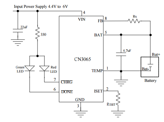
I'm reluctant to connect the load just over the battery terminals since this would presumably upset the charger,
Direct connection of load to battery + charger out is not a totally terrible solution. Whether it is acceptable depends on application and circumstances.
Adding a load will drop even a fully charged battery to < 4.2V and charger will attempt to charge in CC (constant current mode) at whatever current it is set to (as controlled by Riset. If Icc is > Iload the charger will raise the battery + load voltage to 4.2V then change to CV (constant voltage) mode and maintain voltage at 4.2V.
The CN3065 termiantes charging when Icharge = C/10 where C is the programmed charging rate = 1800/RIset.
If Iload > C/10 then the charger will remain in the CV charge mode at 4.2V and the battery will be subject to a constant 4.2V. This will shorten battery life if used in this mode for long periods but may be acceptable in prototype or one-off applications.
If Iload < C/10 then the charge cycle will terminate when Ibattery = (C/10-Iload). This will also shorten battery life but less than in the previous case.
Improved load switch control:
You could drive Q1 with a comparator that compares Vbat with Vin.
When Vin > Vbat + Vextra, Q1 is turned off, where Vextra is enough extra voltage to make up for the drop in D1.
A comparator across D1 will implement this "well enough" - when D1 conducts current is flowing to the load from Vin and the battery can be turned off. When you turn off Q1, if the PV panel cannot support the load its voltage will drop and again enable the battery,
With this scheme (and many other load sharing schemes) there is some risk of oscillation between modes. This can be addressed with hysteresis and addition of a degree of delay in the switching. Operating Q1 in a linear mode rather than on/off so you get a smooth changeover probably helps. Dissipation in Q1 will be small as voltage differential need not be large. For Vin more than say about (V_diode_drop + 0.2V) MOSFET can be fully off. As Vin exceeds Vbat + V_diode_drop MOSFET can start to turn off.

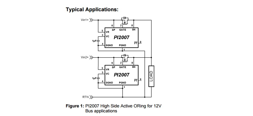
The "ideal" solution is for Q1 and D1 to be "ideal diodes" with minimal voltage drop when conducting. Almost as good is to have D1 as a diode as at present and Q1 replaced with an ideal diode. An ideal diode can be implemented with Q1 and an added opamp or purpose built "ideal diode" controller ICs are available.
These devices implement ideal diodes when used with an external MOSFET such as Q1. I'm not recommending this specific device, but it shows the principle.


