I am trying to recreate this device from:


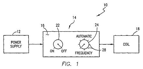
The housing 14 is shown with a control panel 16 for purposes of illustration. In one embodiment of this invention, the control panel 16 includes only an on/off switch 22 which would turn on the circuit 20 allowing the coil 18 to produce a magnetic field at a predetermined, fixed flux density and frequency. Alternatively, the control panel 16 is provided with a control knob 24 coupled to a potentiometer 26 included within the circuit 20, as described below in connection with a discussion of FIG. 2, to permit variation of the output frequency of the circuit 20, and, hence, the frequency of the magnetic field produced by the coil 18. The control knob 24 may be adjusted manually to selected frequency settings, represented by the radial lines 28 on the control panel 16, or, alternatively, to an "automatic" setting in which a programmable microprocessor 30 within the circuit 20 is activated to sequentially vary the output frequency of the circuit 20, as described below.
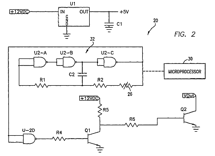
Referring now to FIG. 2, the circuit 20 contained within the housing 14 is shown coupled to the power supply 12 which includes an IC voltage regulator U1 and a filter capacitor C1. The power supply 12 provides a voltage output of 5 volts to an astable multivibrator 32 consisting of NAND gates U2-A, U2-B, U2-C, resistors R1 and R2, capacitor C2 and the potentiometer 26. The operating frequency of the astable multivibrator 32 is determined by the values of R1, R2, potentiometer 26 and capacitor C2, which can be varied over a range of 0.5 Hz to 45 Hz (preferably not beyond 20.1 Hz) by operation of the potentiometer 26.
As schematically depicted with a phantom line in FIG. 2, the circuit 20 may optionally include a microprocessor. As noted above, the microprocessor 20 is operative to sequentially vary the frequency output of the astable multivibrator 32. The selected frequencies over which the output is varied are discussed below in connection with the description of a particular treatment method in accordance with this invention.
The signal from the astable multivibrator 32 is input to the NAND gate U2-D which is configured as an inverter. U2-D is connected through resistor R4 to and NPN bipolar junction transistor Q1 configured as an emitter follower to serve as a level shifter, e.g. to convert the signal from 5 volts to the output voltage used in one embodiment or another. Q2 is an NPN bipolar junction transistor which is coupled to Q1 through resistors R5 and R6. It functions to invert the signal from Q1, thus producing a pulsed or time varying DC output signal in the range of 0.5 to 45 Hz, preferably to no more than 20.1 Hz. When the output signal is coupled to the coil 18, a pulsed magnetic field is produced having a flux density in the range of 0.0001 to 90 gauss depending upon the embodiment of the device 10 and the size of the coil 18 which is coupled to the device at a frequency of 0.5 to 45 Hz, and preferably to no more than 20.1 Hz. Since a DC output signal is provided to the coil 18 by the circuit 20, the north and south poles of the resulting magnetic field do not vary in position relative to the coil 18.
I have replaced the astable multivibrator with a function/arb waveform generator that outputs 0-5 volt dc pulse at 50 milliamps. specs of generator: output amplitude=10vp-p - output impedance=50 ohms - DC bias =+-3v
as in fig. 2 if I put the 5 volt pulse to the base of NPN bipolar junction transistor Q1, and supply the collector with 12 volts - 1 amp, can I expect the output transistor to bring the dc pulse to 12 volts - 1 amp? Is this how the amplifier works?
I've searched the internet to answer this but get confused with all the math. Could someone recommend the proper npn transistor chip to use for this and the values of resistors R4,R5,R6? Trying to get an output of 12v - 1amp dc pulse to the coil.
Please forgive my ignorance. Im not particularly smart and I'm just trying to build one of these pulsers because I cannot afford to buy one. I understand that the transistor part of the circuit is used to amplify the dc pulse just not sure how it is done?
