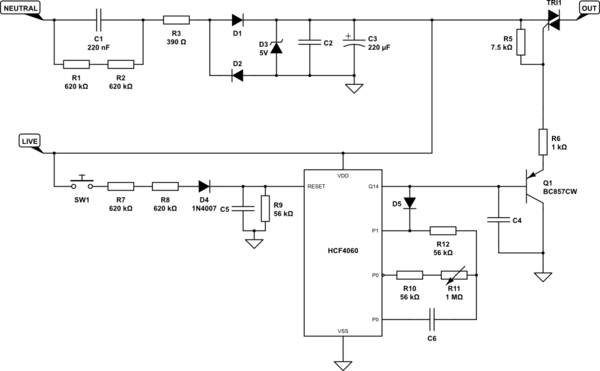
My bathroom fan controller recently started misbehaving, so I pulled its PCB out. This is what I found.

simulate this circuit – Schematic created using CircuitLab
LIVE/NETURAL are the 230 AC mains. I think I have a fairly good grip on what's happening here: the upper part of the system is there to generate 5V for the lower part. The lower part is a 14-bit counter whose most-significant output controls Q1 and therefore TRI1. R10, R11, R12 and C6 together with the invertors integrated in the IC provide a clock, whose frequency can be set by R11. D5 stops the clock once Q14 goes high. In other words, the circuit cuts off the power to the fan after a delay selected by R11.
Now, the user can restart the fan by pressing SW1. I guess the idea is that the switch pulls RESET on the IC high, thus clearing the counter. However, the divider formed between R7+R8 and R9 will make the voltage on RESET only 0.21V! (And yes, I've rechecked the resistor values like 100 times. The two resistors say 624, the R9 says 653; they're all 1206 SMDs.) Yet, somehow, it works (at least it used to).
How?
Furthermore, I've not been able to figure out the intended function of some of the components. I'm guessing that R1 and R2 are there to provide a discharge path for C1 if the mains are disconnected. But what are R3 and C4 for?
