0
\$\begingroup\$

I understand there are two models \$I_c=\beta I_b\$ and $$I_c=I_s \exp \left(\frac{V_{BE}}{V_t}\right)$$ for a bipolar junction transistor.

However (correct me if I am wrong), I have not seen any textbook derivation which actually finds \$\beta\$ as a function of the circuit itself.

Is there some reason for this? I am asking this question because I wanted to know if there could be an expression for this behaviour:
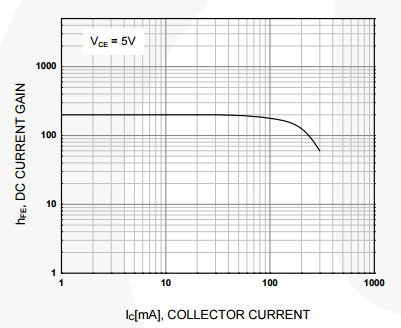
enter image description here

Taken from BC547 datasheet.

In other words, given only \$I_C\$,\$V_{BE}\$,\$I_S\$ (is \$V_{CE}\$ required?) can you work out \$\beta\$ without going out and experimentally finding it?

To begin with (in active region), I think there is a forward biased pn junction between the base and the emitter. Thus it would be a case of finding the diode current (\$I_B\$) for the applied voltage (\$V_{BE}\$)? And then relating this to the \$I_C\$?

Small related question, is the \$I_S\$ in the $$I_c=I_s \exp \left(\frac{V_{BE}}{V_t}\right)$$ stated anywhere in a transistor datasheet?

\$\endgroup\$

5 Answers 5

2
\$\begingroup\$

The equation you are thinking of is from the Ebers-Moll BJT model, simplified for the forward-active operating region:

$$I_E = I_{ES}\left(\exp\left(\frac{V_{BE}}{V_T}\right) - 1 \right)$$

Note this gives the emitter current, not the collector current.

The other two equations in the Ebers-Moll model are

$$I_C = \alpha{}I_E$$

$$I_B = (1-\alpha)I_E$$

Unfortunately these equations don't help you find \$\beta\$ because \$\alpha\$ is just \$\beta\$ in disguise:

$$\beta=\frac{I_C}{I_B}=\frac{\alpha}{1-\alpha}$$

Small related question, is the \$I_S\$ ... stated anywhere in a transistor datasheet?

It's usually not in the datasheet, but if a SPICE model is available for your device, you can get a "typical" value from there. Look for the IS parameter in the MODEL card.

\$\endgroup\$
0
\$\begingroup\$

No, and no.

If you want typical numbers, the datasheet may supply such for beta (under specified conditions). You can find other typical numbers in the SPICE model for the transistor. The same part number of transistor with similar characteristics may have wildly different numbers, especially for Is.

LTSpice model 2N4401: IS=1.75E-12 PSpice model: 2N4401: Is=26.03f

That's 67:1.

\$\endgroup\$
0
\$\begingroup\$

Equation 8.4.5 in the following document gives an expression for BJT current gain:

http://www.eecs.berkeley.edu/~hu/Chenming-Hu_ch8.pdf

However, it is in terms of parameters not readily available for a typical transistor.

\$\endgroup\$
1
  • 2
    \$\begingroup\$ Of course, that's making certain simplifying assumptions. For a short list: running a healthy current (BE-junction recombination is negligible), having a non-graded base (no base drift from built-in potentials), SRH recombination negligible, avoiding high-level injection (Auger recombination, Kirk effect, and base push-out negligible), the collector depletion region has zero width (CE-junction is unbiased), non-ballistic transport... In practice, these assumptions are not true. Summary for the OP: It's complicated. Just measure it. \$\endgroup\$
    – Zulu
    Commented May 19, 2015 at 4:01
0
\$\begingroup\$

hfe is a function of the transistor, not of the circuit it is used in. It's dependent on the particular transistor, and temperature. It varies widly from transistor to transistor of the same type and is strongly affected by temperature. Even if you could find an expression for it, it wouldn't be of that much use, because hfe depends on manufacturing variability, any generic equation you could derive wouldn't include manufacturing parameters and the hfe value produced by the equation would bear little resemblance to the actual hfe of the real transistor produced.

There is so much variation in hfe for BJT's, that you can't rely on an exact figure in a circuit design, (a variation of say 80-200 is possible for some BJTs) and is the reason why many circuit designs employ negative feedback to reduce the gain to a more precise value.

When negative feedback the hfe (or in opamp terminology, open loop gain) can vary greatly, but the gain of the circuit with negative feedback is much more accurately determined.

\$\endgroup\$
0
\$\begingroup\$

In addition to the other posts here, be aware that beta also varies with Vce due to Early effect. This is one of the causes of imperfections in simple current mirrors.

The only practical use of beta in a circuit is to determine the maximum base current required for a given collector current. Ib(max) = Ic / beta(min).

That allows me to determine what transistor may be necessary to meet the available base drive at the input to the amplifier (which is going to be circuit dependent).

\$\endgroup\$

Your Answer

By clicking “Post Your Answer”, you agree to our terms of service and acknowledge you have read our privacy policy.

Not the answer you're looking for? Browse other questions tagged or ask your own question.