13
\$\begingroup\$

Suppose I have a pair of 12-bit ADC's, I can imagine that they can be cascaded to get <= 24-bit output.

I can think of simply using one for the positive range and the other for the negative range, though there probably will be some distortion in the cross-over region. (suppose we can ignore are a few error bits or, perhaps, place a 3rd ADC to measure the value around 0 volts).

Another option I had been thinking of is using a single hi-speed ADC and switching the reference voltages to get a higher resolution at lower speed. Also there should be a way of getting a real-valued result with using one fixed-ref ADC and then switching the aref's of the secondary converter to get more precise value in between.

Any comments and suggestions are welcome.

I am presuming that a quad 8-bit (or dual 12-bit) chip is less expensive then a single 24-bit chip.

\$\endgroup\$
2
  • 2
    \$\begingroup\$ Yes it is possible in theory and in 0.01% of real cases, where parts have "Effectve number of bits" equal to "Data number of bits" with rest of specs comlpying to extra 5 orders of magnitude of accuracy. Which is not true for 99.99% of parts. \$\endgroup\$
    – user924
    Commented Jul 20, 2011 at 16:40
  • 4
    \$\begingroup\$ If you use one for positive voltages, and the other for negative voltages, that only gets you 13 bits. Cascading them would Require a DAC and an amplifier. You convert directly on the signal, write the value to the DAC, and subtract the DAC output from the input signal. Then you amplify the signal by \$2^{12}\$, and feed it into the second ADC. \$\endgroup\$ Commented Jul 21, 2011 at 5:57

6 Answers 6

13
\$\begingroup\$

Lots of things in your question. So lets take them one by one.

Suppose I have a pair of 12-bit ADC's, I can imagine that they can be cascaded to get <= 24-bit output. I can think of simply using one for the positive range and the other for the negative range, though there probably will be some distortion in the cross-over region. (suppose we can ignore are a few error bits or, perhaps, place a 3rd ADC to measure the value around 0 volts).

Not really - you would get 13-bit resolution. One can describe operation of 12 bit converter as deciding in which of the 4096 bins (2^12) inputs voltage is. Two 12bits ADCs would give you 8192 bins or 13-bit resolution.

Another option I had been thinking of is using a single hi-speed ADC and switching the reference voltages to get a higher resolution at lower speed.

Actually this is how Successive Approximation Converter work. Basically one-bit converter (aka comparator) is used with digital to analog converter that is producing varying reference voltage according to successive approximation algorithm to obtain digitized sample of the voltage. Note that SAR converters are very popular and most of ADCs in uC are SAR type.

Also there should be a way of getting a real-valued result with using one fixed-ref ADC and then switching the aref's of the secondary converter to get more precise value in between.

Actually it is awfully similar to how pipeline ADCs are working. However instead of changing reference of the secondary ADC the residue error left after first stage is amplified and processed by next stage ADC.

Any comments and suggestions are welcome. I am presuming that a quad 8-bit (or dual 12-bit) chip is less expensive then a single 24-bit chip.

Actually there is a reason for that as having 24bit converter is not as simple as arranging in some configuration four 8-bit converters. There is much more to that. I think that key misunderstanding here is thinking that one can just "add" number of bits. To see why this is wrong it is better to think of ADC as circuit that is deciding to which "bin" input voltage belong. Number of bins is equal to 2^(number of bits). So 8 bit converter will have 256 bins (2^8). The 24 bit converter will have over 16 millions of bins (2^24). So in order to have the same number of bins as in 24-bit converter one would need over 65 thousands 8-bit converters (actually 2^16).

To continue with the bin analogy - suppose that your ADC have full scale of 1V. Then the 8-bit converter "bin" is 1V/256 = ~3.9mV. In case of the 24-bit converter it would be 1V/(2^24) = ~59.6nV. Intuitively it is clear that "deciding" if the voltage belongs to smaller bin is harder. Indeed this is the case due to noise and various circuit nonidealities. So not only one would need over 65 thousands of 8 bit converters to get 24 bit resolution but also those 8bit converters would have to be able to resolve to 24-bit sized bin (your regular 8-bit converter would not be good enough as it is able to resolve to ~3.9mV bin not 59.6nV bin)

\$\endgroup\$
1
  • \$\begingroup\$ The range a 8-bit converter would work from, is 256*59.6nV = 15.26uV. I never they made reference voltages that low and precise :) \$\endgroup\$
    – Hans
    Commented Aug 14, 2011 at 9:46
14
\$\begingroup\$

Splitting your input range will get you 13 bit, not 24. Suppose you have an input range from -4.096V to +4.096V. Then a 12-bit ADC will have a 2mV resolution: 2\$^{12}\$ x 2mV = 8.192V (the range from -4.096V to +4.096V). If you take the positive half you get 1mV resolution there because your range is halved: 2\$^{12}\$ x 1mV = 4.096V. That's 2\$^{12}\$ levels above 0V, and another 2\$^{12}\$ below. Together 2\$^{12}\$ + 2\$^{12}\$ = 2\$^{13}\$, so that 1 bit extra, not 12.

About changing the reference voltage. I'll give a different example. Suppose you have a 1 bit ADC and want to get 12 bits by changing the reference. One bit will give you a 1 if the input is greater than \$\frac{V_{REF}}{2}\$, and a zero otherwise. Suppose your reference is 1V, then the threshold is 0.5V. If you change your reference to 0.9V you'll have a new threshold at 0.45V, so you're already able to discern 3 different levels. Hey, this may work, I can do 12-bits with a 1-bit ADC, and then probably also 24-bit with a 12-bit ADC!
Hold it! Not so fast! You can do this, but the components of your 1-bit ADC have to be 12-bit grade. That's for the precision of the reference, and the comparator. Likewise, a 12-bit ADC would be able to do 24-bit if the precision of the ADC is precise enough, and that the precision of the varying reference voltage is 24-bit grade. So in practice you don't gain much.

There's no such thing as a free lunch.

edit
There seems to be a misunderstanding about oversampling, and the fact that there are 1-bit audio ADCs which can give you 16-bit resolution.
If your input is a fixed DC level, say 0.2V in a 1V input range, your output will always be the same as well. With a 1-bit ADC this will be zero for our example (the level is less than half the reference). Now that will be so, whether you sample at 1 sample per second, or 1000. So averaging doesn't change this. Why does it work with the audio ADC?, because the voltage varies all the time (noise), which, according to Einstein (relativity, you know ;-)) is the same as keeping the voltage constant and varying the reference. And then you get several different readings while oversampling, which you can average to get a quite good approximation of your actual level.
The noise has to be strong enough to pass the ADC's threshold(s), and has to fit certain constraints, like Gaussian distribution (white noise). In the 1-bit example it didn't work because the noise level is too low.


Further reading:
Atmel application note AVR121: Enhancing ADC resolution by oversampling

\$\endgroup\$
7
  • \$\begingroup\$ I'm not sure I understand your thinking on that. Surely if you split + and - you can then sample at 0v to +4.096v at 12 bits and 0v to -4.096v at 12 bits making a total of 24 bits over the full range? \$\endgroup\$
    – Majenko
    Commented Jul 20, 2011 at 15:34
  • 1
    \$\begingroup\$ @MattJenkins, it would be the same as a sign bit. Think about it. If I sample 0-10V with 12 bits and 0-(-10V) with 12 bits I only need one bit to say if the signal was negative or positive. \$\endgroup\$
    – Kortuk
    Commented Jul 20, 2011 at 15:38
  • \$\begingroup\$ This is true - so although you could sample as 24 bits, you could get the exact same resolution with just 13 bits. \$\endgroup\$
    – Majenko
    Commented Jul 20, 2011 at 15:43
  • \$\begingroup\$ @Matt - every doubling of resolution gives you 1 bit extra. 2 bits over 8V give you 2V resolution (\$\frac{8V}{2V} = 2^2\$), a third bit gives you half of that, 1V (\$\frac{8V}{1V} = 2^3\$). \$\endgroup\$
    – stevenvh
    Commented Jul 20, 2011 at 15:44
  • \$\begingroup\$ @MattJenkins, you could use 1 hot encoding and take 1024 bits instead of 10. The physical reality is that the engineer can do whatever he wants, just tell the customer you are only off by 3dB, not 10kW. \$\endgroup\$
    – Kortuk
    Commented Jul 20, 2011 at 15:50
3
\$\begingroup\$

Yes, in theory you can do what you want, but only if you have some wholly unrealistic equipment available to you.

The several other comments made so far about limited extra accuracy are correct, alas.

Consider. Measure a voltage with a 12 bit ADC and get say 111111000010 You know that the real value lies somewhere in a 1 bit range +/- 0.5 bits either side of this value.

IF your ADC was accurate to 24 bits but was providing only 12 bits then it is reporting that the vaklue lies within +/- half a bit of 111111000010 000000000000. If this was the case you could take a 12 bit ADC with a +/- 1/2 bit range, centre it on 111111000010000000000000 and read the result. This would give you the difference bwteen the actual signal and the aDC value, as desired. QED.

However the 12 bit ADC is itself only accurate to about half a bit. The sum total of its various errors cause it to declare a certain result when the real result is up to about half a but different plus or minus.

While you would like

111111000010 to mean 111111000010 000000000000

it may actually mean 111111000010 000101101010 or whatever.

SO if you then take a 2nd ADC and measure the lower 12 bits and ASSUME that they are relative to an exact 12 bit boundary, they are actually relative to the above erroneous value. As this value is essentially random error, you would be adding you new 12 lower bits figure to 12 bits of essentially random noise. Precise + random = new random.

EXAMPLE

Use two conveters that can measure a range and give a result in 1 of 10 steps. If scaled to 100 volt FS they give ge 0 10 20 30 40 50 60 70 80 90

If scaled to 10 volt full scal they give 1 2 3 4 5 6 7 8 9

You decide to use these two converters to meaure a 100 volt range with 1 volt accuracy.

Converter 1 returns 70V. You then measure the voltage relative to 70V and get -3V. So you conslude that the real value ie +70V - 3V = 67V.

HOWEVER the 70V result could in fact be any of 65 66 67 68 69 70 71 72 73 74

Only if the 1st converter is ACCURATE to 1V in 100, even though it displays 10V steps in 100V, can you achieve what you want.

So you real result is 67V +/- 5 volt = anything from 62V to 72V. So you are no better off than before. Your centre has moved but it may be located randomly.

You will be able to get modest improvement this way as a converter is usually probably slightly more accurate than the bits it returns (you hope) so your 2nd converter makes some use of this.


A system that does in fact work has been mentioned with one important omission. If you sample a signal N times and you add +/_ half a bit of gaussian noise you will spread the signal "all over the possible range" and the average value will now be log(N) more accurate than before. This scheme has fishhooks and qualifications and you cannot just get an arbitrary extra number of bits, but it does offer some improvement.


In the first case above I mentioned a12 bit ADC with 24 bit accuracy. You can achieve something of th sort by using a 12 bit ADC and reading its assumed value with a 24 bit eg delta sigma converter. IF the signal was stable enough that it remained in the same one bit range you can use a 2nd ADC to read the 2nd 12 bits wrt this stable signal.

Alternative - just read 24 bit signal initially with sigma delta, lock in that point and then mesure successively relative to it with the 2nd ADC.As long as the signal stays within range of the 2nd ADC you'll get a much faster result.

\$\endgroup\$
1
  • \$\begingroup\$ Hmmm. One up vote. One down vote. Given what passes for OK answers here [tm] :-) I'd be interested to know who thought this answer was so terrible as to merit down voting, and why? \$\endgroup\$
    – Russell McMahon
    Commented Jul 20, 2011 at 19:36
1
\$\begingroup\$

There is something called supersampling which can be used to increase the resolution of many types of ADC.

It works by adding noise to the signal. Although the noise reduces the resolution, it is necessary to cause the data to split itself over several bits. (I'm not a signal processing guy - this is just how I understand it.) Your noise might only be 1 or 2 bits but it needs to be there. If you take one 12-bit sample - you have 12 bits. If you then take 4 samples, add them together and divide by two, you get a 13 bit sample. (Each additional bit requires 4 samples, due to Nyquist.)

A simple way to do this is to add noise to the reference voltage. I use this to boost a 12-bit ADC in a dsPIC33F to 16-bit for higher resolution. Beforehand, I set up an asynchronous timer at a high frequency and use DMA to queue a sequence of PRNG numbers into the output capture which gives a relatively clean source of noise. The noise output biases the reference voltage by about 0.1% (1k-1Meg divider.) The noise is bidirectional, sinking and sourcing. I use the dsPIC33F's DMA to queue samples so this can be done with little CPU intervention. Of course the maximum sample rate drops to around 1/32th the normal rate, but this isn't a problem for my application.

As the noise isn't always uniformly distributed I will be calibrating the inputs on every unit which is shipped, although the difference is likely to be only 1 or 2 LSB.

\$\endgroup\$
6
  • \$\begingroup\$ How do you know the noise you add has the right spectrum (is white noise)? How do you decide on the amplitude? If your noise isn't good then you'll have more resolution, but not more accuracy. \$\endgroup\$ Commented Jul 20, 2011 at 17:11
  • \$\begingroup\$ @Federico Of course - for me, it's trial and error. White noise can be simulated using a PRNG and for only 32 samples it works well enough. If I were an actual electronics engineer, I would know how to do it properly. \$\endgroup\$
    – Thomas O
    Commented Jul 20, 2011 at 17:53
  • \$\begingroup\$ Here's an article at Analog Devices that might help explain this: analog.com/library/analogdialogue/archives/40-02/adc_noise.html \$\endgroup\$
    – DarenW
    Commented Jul 20, 2011 at 18:06
  • \$\begingroup\$ @ThomasO, I have used this technique with thermistors to add 8 bits of precision. Not with noise though, we used heating. \$\endgroup\$
    – Kortuk
    Commented Jul 20, 2011 at 18:10
  • \$\begingroup\$ @DarenW That looks familiar - I think it's where I got my idea from. \$\endgroup\$
    – Thomas O
    Commented Jul 20, 2011 at 22:04
1
\$\begingroup\$

Using summing amplifier you can sum the two DAC outputs. You can use R1=100k, R2=R3=100 Ohm. This way the output will be Vout = -(V1 + V2 / 1000). You'll need dual supply and if you want it non-inverted you need to put another inverting amplifier with gain = 1. So let's say you have 12 bit DAC with 2 outputs and reference 4.096V. Then (if you have second inverting amplifier) one increment from DAC 1 will increase output with 1uV, and one increment from DAC 2 will increase the output with 1mV. That's not 24 bit in total. It's about 22 bits. In theory you you can choose R1 to be 4096 times bigger than R2 and R3 and get 24 bits, but You won't get better results. You'll have a lot of noise problems in microvolts range even if you pick a good low noise opamp.

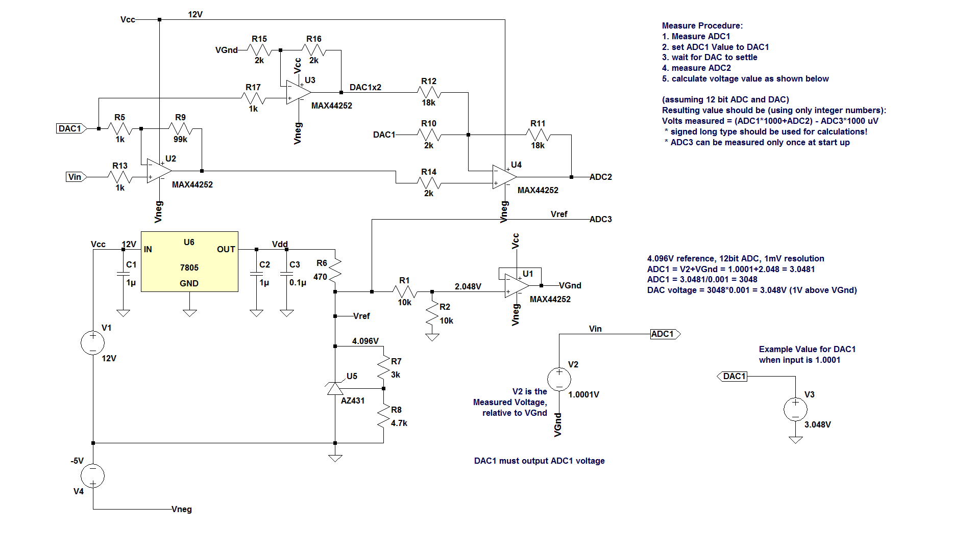
Update I though it's a question about DAC because I was searching for DACs. Here is how you apply similar principle with ADCs. Instead of summing you have to subtract ADC1 result then multiply by 1000 before measure with ADC2.

Double ADC Resolution

Correction - ADC3 should be on VGnd (Vref/2), not Vref to match the result formula

Instead of AZ431 you can use any other 2.5V reference or another adjustable reference with proper passives to get exactly 4.096V. The less temperature drift the reference has, the better the results. Also it has to be low noise. Note that as is it's probably not accurate enough. It'll be nice to put 500 ohm multi turn trimpot between R7 and R8 with wiper to the reference input and tweak it for Vref = 4.096V exactly. Also a trimpot(2) will be needed between R1 and R2 with wiper to U1 positive input. Tweak it for 2.048V on VGnd. U1 is just any low noise opamp. (BTW AZ431 is awful for the job. I put it because I had the symbol).

It's very critical for U2, U3 and U4 to be zero offset chopper amps. U2 is more important because it multiplies by 100. every 1 microvolt gets to 100 microvolts. If you use OP07 and you zero it properly and the temperature changes with 10 degrees then you get 13 uV offset which translates to 1.3 mV on the output of U4. That's 13 mV in ADC output which makes ADC2 almost useless.

Also U3 must be able to reach 6.048V - that's VGnd(2.048V) + 2xVinmax (2x2V=4V). That's the whole idea of having Vcc = +12V power supply. Vcc can be as low as 6.5V when MAX44252 is used. Since MAX44252 is rail to rail opamp negative supply can be skipped and Vss of the opamp can be connected to ground. That's true for any opamp that can go as low as 48mV on it's output.

MAX44252 has 2-4uV offset voltage (typical) and 1 to 5 nV temperature drift. It's $2.64 on digikey in quantities of 1 and it's quadopamp so only one chip will do the job.

How it works? Let's have 10bit DAC for example. Resolution is 4.096/1024 = 4mV. Input signal must be relative to VGnd, which is half of Vref. ADC1 measures input voltage as normal. Then outputs the value via DAC1. The difference between Vin and DAC1 is the error that you need to amplify, measure and add to the ADC1 result. U2 amplifies the difference Vin - DAC1, relative to DAC1, with gain of 100. U4 amplifies that difference by 10 and also subtracts DAC1, relative to VGnd. That makes ADC2 = (Vin - DAC1) * 1000, relative to VGnd. In other words if you have 1.234567V on Vin, relative to VGnd. ADC1 will measure value of 821 because resolution is 4mV and (2.048+1.234567)/0.004 = 820.64175. So the DAC value will be set to 309 which is 309*0.004V = 1.236V. Now ADC2 will get 1.234567-1.236=-0.001433*1000 = -1.433V relative to VGnd (ideally). That's 2.048-1.433=0.615V common mode. 0.615V / 0.004 = 153.75. So ADC2 value = 154. It's easier to calculate value in microvolts to avoid using float. to convert ADC2 in mV we have to multipy the value by 4: VADC1 = 821*4 = 3284mV. To convert to uV we need to multiply by 1000. Or that's ADC1 value multiplied by 4000. 821*4000 = 3284000. So ADC1 voltage with respect to VGnd is 3284000-2048000 = 1236000uV. The ADC2 is already multiplied by 1000 so we need to multiply only by 4: VADC2 = 154*4 = 616. To get voltage relative to VGnd we need to subtract VGnd: 616-2048 = -1432uV. We take VGnd = 2048uV here because we have x1000 amplification.Now we add VADC1 and VADC2: 1236000 + (-1432) = 1234568uV or 1.234568V

Of course that's just dreams because when you deal with microvolts there will be all kinds of horrible problems - opamp noise, resistors noise, voltage offset, temperature drift, gain error ... But if you use decent parts, at least 1% resistors and you programmatically null the offset and correct the gain you might get reasonably good result. Of course you can't expect to see stable input to the last digit. maybe you can limit the resolution to 10uV (divide the result by 10). Also the multiply by 4 can be done by summing 4 sequential results to have some averaging.

Keep in mind that nothing of this is tested. I simulated only the amplifier stage without taking into account noise and opamp offset. If someone decides to build it write the results in the comments.

\$\endgroup\$
7
  • \$\begingroup\$ Question asks about ADC. You talk about DAC. \$\endgroup\$
    – dim
    Commented Jan 9, 2017 at 5:28
  • \$\begingroup\$ I'm sorry. I searched for DAC and I found this question. I wrote without carefully reading. I'll compensate suggest how to apply the same principle to ADC. \$\endgroup\$
    – NickSoft
    Commented Jan 10, 2017 at 16:26
  • \$\begingroup\$ I removed my downvote, since your post is now related to the question. But I don't think this solution can work in practice. I'm afraid there will be too much inaccuracies. \$\endgroup\$
    – dim
    Commented Jan 10, 2017 at 20:12
  • \$\begingroup\$ Of course it will work. However the accuracy depends on the used parts. There are chopper amps that have 0.1uV offset and 1-5nV/degC drift. Also they have nanovolts 0.1-10Hz p-p noise. Combined with a good reference it could get a stable output up to 10s of uV. But this can work with cheaper parts if you want to gain extra digit. For example 10 bit ADC is with 4.096V reference has 4mV resolution. I think with this circuit it can be improved to 0.1uV resolution with ease (maybe with better reference). That's +/-20000 counts. Of course it'll need software calibration for offset and gain. \$\endgroup\$
    – NickSoft
    Commented Jan 11, 2017 at 9:28
  • \$\begingroup\$ That is all theory. The fact that your ADC2 reading depends on your DAC setting (and opamp offset, but this is not even the most crucial part), that depends itself on your ADC1 reading (and all these having tolerances), will lead to the fact you certainly won't be able to even guarantee monotonic operation of your system (even if you're within the bounds of your calculated accuracy). \$\endgroup\$
    – dim
    Commented Jan 11, 2017 at 9:57
0
\$\begingroup\$

Depending on the nature of your signal, you can use the higher speed, lower resolution ADC, but you don't need to move your reference voltage around (I'd inspect the data sheet carefully to see if you could even get away with that). You just need to do some post processing afterwards; it's called Oversampling. Short hand wavy story: increase your sampling rate by a factor of a lot, and get \$log_2 (\text{a lot})\$ more bits of resolution.

edit: see the comments for corrections to my math.

\$\endgroup\$
6
  • \$\begingroup\$ That's what I thought as well, but consider this: 1V input range, 0.2V input, 1-bit ADC. No matter how high your oversampling you'll always read 0, average = 0, not 0.2. \$\endgroup\$
    – stevenvh
    Commented Jul 20, 2011 at 15:48
  • \$\begingroup\$ Oversampling like that will require some "noise" on the signal. As stevenvh pointed out. Sometimes the signal itself has enough "noise" on it to accomplish this without anything new. Other times you need to inject some high frequency noise into the signal-- but the noise will be filtered out in the post-processing that you do afterward. \$\endgroup\$
    – user3624
    Commented Jul 20, 2011 at 15:57
  • \$\begingroup\$ Right, well, "depending on the nature of your signal". The question doesn't say if he's reading the temperature from a thermistor glued to the side of a lead brick, or if he's sampling mixer output for SDR. So he got another option. If anyone can provide a pointer to the exact mathematical properties the signal needs for oversampling to be valid, I'd be really interested, btw. (And that seems like it would be a useful addition, instead of, sorry, corrections which are only somewhat less hand wavy than my original statement.) \$\endgroup\$ Commented Jul 20, 2011 at 16:34
  • \$\begingroup\$ @Jay - I think you get \$log_2 (a lot) - 2\$ more bits. \$\endgroup\$
    – stevenvh
    Commented Jul 20, 2011 at 17:26
  • \$\begingroup\$ My primary interest is in audio signals, so I though that once 24-bit converters are quite expensive and not so many of them exist, may be cascading more widely available converters will work. Thanks everyone for in-depth explanation. It does sound possible at first, doesn't it? :) \$\endgroup\$ Commented Jul 21, 2011 at 9:25

Your Answer

By clicking “Post Your Answer”, you agree to our terms of service and acknowledge you have read our privacy policy.

Not the answer you're looking for? Browse other questions tagged or ask your own question.