0
\$\begingroup\$

schematic

simulate this circuit – Schematic created using CircuitLab

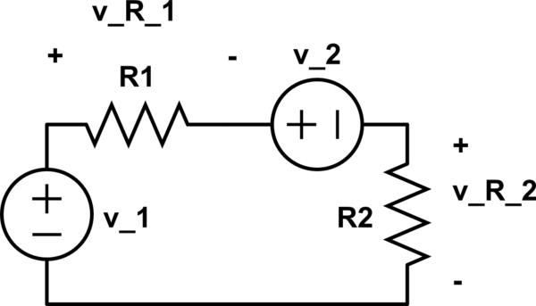
Why is \$v_{R_2}=(v_1-v_2)\frac{R_2}{R_1+R_2}\$ ?

Could anybody show me this formula, please?

\$(v_1-v_2)\$ is the voltage across \$R_1\$, which is divided between \$R_1\$ and \$R_2\$. I can't fully understand myself this last sentence.

EDIT:

I also tried to solve it this way:

The starting circuit is equivalent to this:

schematic

simulate this circuit

which is equivalent to this:

schematic

simulate this circuit

Thus the current on \$R_2\$ is \$(\frac{v_1}{R_1}+\frac{v_2}{R_2})\frac{R_1}{R_1+R_2}\$ and the voltage \$v_{R_2}=R_2\cdot (\frac{v_1}{R_1}+\frac{v_2}{R_2})\frac{R_1}{R_1+R_2}=v_1 \frac{R_2}{R_1+R_2}+ v_2 \frac{R_1}{R_1+R_2}\$

What's wrong here?

\$\endgroup\$

3 Answers 3

3
\$\begingroup\$

Another way to skin this poor cat!

Using Kirchhoff's voltage law (KVL) and Ohm's law you can write the following equation, where \$i\$ is the current in the mesh (clockwise direction):

\$ v_1 - R_1\,i - v_2 - R_2\,i = 0 \$

From this you get:

\$ i = \dfrac{v_1 - v_2}{R_1 + R_2} \$

Apply Ohm's law to \$R_2\$ and you'll find the answer.

EDIT (In response to OP editing his question)

You cannot apply equivalent circuit substitution that way. When you substitute a circuit section with an equivalent one, only the quantities external to that section are guaranteed to stay the same. When you substituted \$v_2/R_2\$ with its Norton equivalent, you lost track of the nodes across which you wanted to calculate the voltage (they disappeared inside the equivalent circuit).

If you want to go the route of Thevenin/Norton equivalence, you could substitute the series \$v_1, R_1, v_2\$ with its Thevenin equivalent: \$v_{Th}\$ (the open circuit voltage) in series with \$R_{Th}\$ (the resistance you see when you disable the voltage sources - i.e. substitute them with short circuits). You get then:

\$ v_{Th} = v_1 - v_2 \qquad R_{Th} = R_1 \$

Note that \$R_2\$ wasn't touched in this substitution, thus the voltage across its terminals will remain the same. Therefore now you have \$v_{Th}\$ in series with \$R_1\$ and \$R_2\$, so you've got a voltage divider with \$v_{Th} = v_1 - v_2\$ total applied voltage, so you get:

\$ v_{R_2} = v_{Th} \dfrac{R_2}{R_{Th} + R_2} = (v_1 - v_2) \dfrac{R_2}{R_1+R_2} \$
\$\endgroup\$
1
  • \$\begingroup\$ thank you @Lorenzo Donati. Could you check out my edit, please? \$\endgroup\$
    – sl34x
    Commented May 25, 2015 at 13:21
1
\$\begingroup\$

As far as R2 is concerned, it can't tell that there are two voltage sources so, the net voltage source is V1 - V2 because they are opposing sources. This difference voltage then drives the potential divider formed by the two resistors.

\$\endgroup\$
1
  • \$\begingroup\$ Could you please draw-me an equivalent circuit to better understand it? Also: I noticed that \$v_{R_2}=v_1-v_2 - v_{R_1} = v_1 - v_2 - v_1+ v_2 =0 \$. Is this right? \$\endgroup\$
    – sl34x
    Commented May 25, 2015 at 10:36
0
\$\begingroup\$

$$ V_{R_2} = I × R_2 \ \ \ (1)$$

$$ I = \frac {V_T} {R_T} \ \ \ (2)$$

Substitute (2) into (1) and rearrange.

$$ V_{R_2} = \frac {V_T} {R_T} × R_2 = {V_T} × \frac {R_2}{R_T} \ \ \ (3)$$

It is a series circuit with two sources with opposite signs, so:

$$ R_T = R_1 + R_2 \ \ \ (4)$$ $$ V_T = V_1 - V_2 \ \ \ (5)$$

Substitute (4) and (5) into (3).

$$ V_{R_2} = {V_T} × \frac {R_2}{R_T} = {(V_1 - V_2)} × \frac {R_2}{(R_1 + R_2)}$$ $$ V_{R_2} = {(V_1 - V_2)} × \frac {R_2}{(R_1 + R_2)}$$

\$\endgroup\$

Your Answer

By clicking “Post Your Answer”, you agree to our terms of service and acknowledge you have read our privacy policy.

Not the answer you're looking for? Browse other questions tagged or ask your own question.