4
\$\begingroup\$

1$ color sensor.

My adventures in electronics continue. While talking with a friend about colors, he told me about color sensors. Later I remembered the video where they sort smarties and so I wanted to know more. Watching some videos I found one with a LDR and a RGB led. They say it's not precise. Looking at the various builds of those sensors I guess that part of the problems are the case that holds everything together. Most of them have a lot of space between the LDR and the colored surface, some have the leds in front of the LDR... that cannot work.

  1. There should be no other light source than the RGB led. Put the LDR and RGB Led inside a small tube, inside needs to be black. I couldn't find a tube made of this material. so I took a thick Pen.
  2. Direct lightning of the rgb should be avoided. To get a nice homogeneous color I put a white semitransparent piece of plastic in front of the Led.

  3. The LDR should only get the reflected light. Put the sensor on top of the white plastic. The light needs to be behind the LDR!.

  4. It cannot work for everything. You can use it for only specific surfaces. For example I use glossy photo paper. Opaque would be better probably. but I had some photopaper in the printer and so I printed a colorpalette & a black and white palette.

  5. You need to know more about the Led & LDR. That is basically the problem. The Red, Green and Blue emitted by the led are not 100% red green and blue. The LDR cannot absorb every color perfectly .

Without looking other codes I hooked up this color sensor pen to the arduino... and measured how much time it needs to turn on the various colors. I ended up with 50ms for each color. Done that I just let the LDR print some values on the screen. Black and white... how much range do I have from black to white? I wrote a code where it autocalibrates the black and white. Basically I measured the light asbsorbment on the previously printed black and white photo paper. I was actually impressed how much range i could have. From the total of 1023 range aviable on the arduino I go a black of around 30-50 on all colors and a white around 700. That means the color sensor has a theoretically precision of, let's say an average range of 650 on each color, 650*650*650 =274.625.000, around 270 million colors. Thats alot ...rgb has 16million colors. I personally know about 5-6 colors. At that point I started to test. to make it simple I placed another rgb led on the board and a white plastic hut on the led. The colors appeared already similar but to much lighness. Also on dark surfaces I got the led turn on. I then decreased the range at about 10% at the bottom and 10% from top. And wow.. color looks the same. But lets see the numbers. Printing the rgb values on screen gave different numbers than those I measured ... but opening a rgb color selector on screen and displaying it... showed approximately the right color ... so it was actually very correct.Even if my printer is a photoprinter it does not means that the colors are printed correctly. I never calibrated a printer or a monitor...So there can be a big difference. So I tried to calibrate the various colors based on the printed palette. Turned the red light on and decreased the range of green and blue to 0 while on red... the same for grren and blue.I finally found the real problems. The red is almost perfect. The blue is slightly shifted towards the red. The green has not enough light? When on green I need to put the red and blue levels very low. But doing that drops the precision a lot . I get perfect red(255,0,0), blue(0,0,255), green(0,255,0), yellow(255,255,0),fuchsia(255,0,255),aqua(0,255,255). the range of every color is dropped so much that at the end I probably can measure only about 10-15 main colors.

How could I calibrate a 1$ color sensor?

  1. Every led color is shifted slightly.

  2. The green does not output enough light.

  3. My printer didn't print the right colors.

  4. The LDR does not read every color correctly (wavelength,light....)

I think somewhere out there is a mathematical calculation that allows the vitrual shifting of each color.

I posted this here because it's a vast question that needs the basics of electronics engineering. While I think most problems could be solved with a complex mathematical function I could be wrong and solve the problem with some simple dimming of the led, adding more leds, maybe filter the light source or just move the sensor up or down inside the tube.what about just by changing the resistors?. In all cases a electronic engineer is needed. The way the leds emit the light and the sensor absorbs it has to do with the individual wavelength...i'm not an electronical enginer.

I think also it's worth to ask because of the fact that color sensors are normally not that cheap.

RGB led: LL0548RGB

LDR: FW300

Short clip that shows the sensor

\$\endgroup\$
7
  • \$\begingroup\$ Can you make your question more concise? By the way, have you looked at the datasheet for the LED and LDR. The LED datasheet will have the wavelength of each R, G and B component and the LDR datasheet will have its spectral response. \$\endgroup\$ Commented Jun 1, 2015 at 15:59
  • \$\begingroup\$ yes exactly that!! i don't know how to apply that values. \$\endgroup\$
    – cocco
    Commented Jun 1, 2015 at 16:00
  • \$\begingroup\$ on the leds i only need the nm ... right? not the mcd.At the other side the LDR has not much info in the datasheet \$\endgroup\$
    – cocco
    Commented Jun 1, 2015 at 16:02
  • \$\begingroup\$ also the leds' have not the best info ... for example what is the best voltage for every color??? it says only 2.1 to 3.2. so it's also hard to decide for the proper resistor... normally r = 2.1 g= 3.1 b= 3.2 \$\endgroup\$
    – cocco
    Commented Jun 1, 2015 at 16:07
  • \$\begingroup\$ Not to rain on your parade, but color sensors have gotten very cheap these days. \$\endgroup\$ Commented Jun 1, 2015 at 16:20

2 Answers 2

6
\$\begingroup\$

You are attempting to map a triplet of values (the responses of the LDR to your RGB LEDs) to another triplet (the RGB values you used to print the colors on the paper). There are loads of environmental values that will influence this mapping. IMO the best you can do is

  • Make sure each LED gives a decent and compareable effect. Depending on your LEDs and the sensitivity of your LDR to the various colors, this might mean that you have to use different currents (series resistors) for the LEDs.

  • Establish the calibrarion values for your colors (as you have done) and use this to 'linearize' the R, G and B values.

  • Limit the external effects to a minimum. (you seem to have done this)

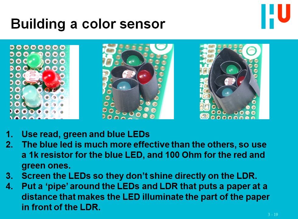
I use exactly this as an excercise for my students. I have reputation of not being easdy on my students. They pass when the can reliably distinguish 3 colors :) One sheet from that assignment:

enter image description here

\$\endgroup\$
3
  • \$\begingroup\$ Than you for your answer, so your saying that if i change the resistors i get different rgb tonalities ? thats a start. for the rest i think that the build showed on your picture has alot more environmental problems than the tube i use. btw like i said i'm not a electronical engineer. And by telling me to 'linearize' the R, G and B values the problems is for shure not solved."Make sure each LED gives a decent and compareable effect" same as above... HOW? \$\endgroup\$
    – cocco
    Commented Jun 1, 2015 at 16:27
  • \$\begingroup\$ like i said i got very nice results from black to white 60-70 % of the maximum. the red green and blue are not calibrated... i also think that at the end there needs to be used a curve to mix colors perfectly... so nothing linear until there is no perfect red, green and blue. \$\endgroup\$
    – cocco
    Commented Jun 1, 2015 at 16:33
  • \$\begingroup\$ @geometrikal talked about the spectral response & wavelength of the individual colors... thats something that more realistically talking could make a difference. \$\endgroup\$
    – cocco
    Commented Jun 1, 2015 at 16:36
2
\$\begingroup\$

1) You don't actually need to know the exact voltages for each color. Just pick a handy set of numbers and stick with it. Most likely, you are using a single voltage for all 3 LEDs, with a different resistor for each color. You don't have to use the same resistance for each LED. In particular, you can use a smaller resistor on the green in order to get more brightness. How small? That will depend on the LED, and you MUST learn to calculate the relationship between voltage, current and resistance. It's called Ohm's Law, and this response is not the place to start teaching it.

2) You don't need to know the exact response for the LDR, either. All you need to know is the relative response for different light levels of each color. You can do this by calibrating your responses. Since you're using an Arduino, do not just turn on and off the 3 LEDs, as you are doing now. Instead, PWM them to get differing light levels, and use a "standard" white target (it's standard because you say it is - it's YOUR standard). Drive the LEDs with different light levels, equal to the PWM duty cycle, and record the LDR output. LDRs are quite slow. I recommend increasing your on-time for each color to .1 second, and take your LDR reading at the end of that time. From this, you can set up a table of how much light at a given color corresponds to each LDR reading.

3) You can use your LDR to calibrate your output LEDs. Shine the output LED into your LDR (making sure to keep ambient light out with a sleeve around them). Drive the output LEDs to different levels, and record the LDR output. You can use this to compensate the output so that for a given sensor LDR reading, you get the same reading when the LDR is looking at the output.

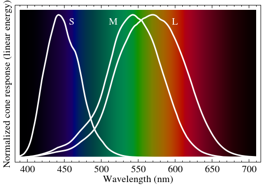
4) Finally, you can never get perfect response in the real world, especially with your setup. Consider what would happen if your color sample were a pure yellow. It reflects only yellow, so it will not respond to any of your three LEDs, and the sensor will report that it is black. In this case, it's a good thing that your LEDs are not pure colors, and that very few real materials have super-pure color reflectance. For what it's worth, the human eye doesn't have extremely selective color receptors either. From http://en.wikipedia.org/wiki/Color_visionenter image description here you can see that there is a lot of color overlap between the three receptor types. And just to make life interesting, there are some colors which simply cannot be reproduced by 3 colored LEDs - brown, for instance.

\$\endgroup\$
11
  • \$\begingroup\$ good.. get +1 for the nice long answer.. 1.led.linear1.org/1led.wiz i used that and made another to calculate ohms more precisely so i can mix various resistors to get out the maximum... i measure those values with my multimeter.2.pwm yep i could use the 980hz pins on the green and the blues to have more playground. but this also implies more readings. With simple high low i get a very stable value after 3 readings. with pwm... dunno... worth a try will tell you next days.3. the tube is pretty insensitive to external envoirements. the light is nicely dimmed and the values stay precise. \$\endgroup\$
    – cocco
    Commented Jun 1, 2015 at 17:12
  • \$\begingroup\$ i calibrate the lightness with the ldr... but like you know the tonality is incorrect. 4. Naturally it cannot be perfect but i think considering the high range given from black to white i have good chances to output maybe thousends of colors if i can calibrate the red green and blue correctly. i test this in the next days... with pwm & resistors. then i give a look in those spectrum curves... \$\endgroup\$
    – cocco
    Commented Jun 1, 2015 at 17:15
  • \$\begingroup\$ @cocco "yep i could use the 980hz pins on the green and the blues to have more playground. but this also implies more readings." First, you need to do it on all 3 LEDs. Second, yes it takes more readings, but you only have to take them once, during calibration. As a matter of fact, you could write a program to do it automatically while you do something else. \$\endgroup\$ Commented Jun 1, 2015 at 17:34
  • \$\begingroup\$ arduino has only 2 980hz pins... i could multiply the 480hz's but the red alreadys appears to be the most correct.and by multiplying the 480hz i don't have exactly the same hz on all 3 leds...anyway as it takes 50ms to turn the led fully on also 50hz would be enough.to get a readable dimmed light. the pins use different timers... and some of them are used to measure the time! millis(); it's better to leave them as they are. \$\endgroup\$
    – cocco
    Commented Jun 1, 2015 at 17:37
  • \$\begingroup\$ " as it takes 50ms to turn the led fully on also 50hz would be enough". Wrong on several counts. The LED will turn on in a microsecond or less. 50 msec is equivalent to 20 Hz. And it's the LDR response which is the limiter. If you are measuring resistance to better than 1% of the available range, 50 msec is almost certainly not enough time. \$\endgroup\$ Commented Jun 1, 2015 at 17:41

Your Answer

By clicking “Post Your Answer”, you agree to our terms of service and acknowledge you have read our privacy policy.

Not the answer you're looking for? Browse other questions tagged or ask your own question.