6
\$\begingroup\$

I have already looked at this question which looked like it would provide the answer:

How to choose a flyback diode for a relay?

But it didn't, so I also checked out these:

Which didn't either. So my question is:

When selecting a flyback diode for a relay, how can I determine whether the speed of the diode is adequate for the application?

I am not looking for diode suggestions, but rather:

  1. What specifications in the datasheet for a diode I would need to look at
  2. How I can calculate the required values from 1. , given whatever information is needed about the circuit that controls the relay coil, and the specs of the relay.

I presume it has to do with capacitances in the diode's datasheet among other things.

Thanks

Edit: to clarify, I don't mind if the relay takes some time to turn off. What I am concerned with is ensuring protection of the controlling circuitry from the spike the coil generates when current to it from the controlling circuitry ceases.

\$\endgroup\$

4 Answers 4

16
\$\begingroup\$

This has nothing to do with a relay, other than its coil acts like a inductor. What you are really asking is how to chose the flyback diode across a inductor.

There are three main parameters to look at:

  1. Voltage rating. This is the maximum voltage the diode can take across it backwards, and still block current and not get damaged. This must be at least the maximum voltage applied to the coil.

  2. Current rating. The maximum current thru the diode will be the same current that is going thru the coil when the coil drive is shut off abruptly. The maximum coil current must already be known to design the coil driver. Ideally the diode should be rated for at least this current.

    However, many diodes allow significantly higher currents for short times than the maximum allowed continuous current. This can be relevant in the case of a flyback diode. Flyback current will decay on its own, so if the coil is shut off only occasionally, it can be valid to consider the pulse current spec instead of the continuous current spec. If you are not sure how to calculate all this, use the continuous current rating.

  3. Reverse recovery time. This is how long it takes the diode to switch from conducting to non-conducting mode. If forward current is going thru a diode and you instantaneously change the voltage so that the diode is reverse biased, the diode will actually conduct in the reverse direction for a little while before it shuts off.

    Now think of when this situation occurs when driving a coil. If the coil was recently turned off and the flyback current is still flowing thru the diode and the coil driver is switched on again, then there is a short from the power supply thru the diode thru the coil driver until the diode catches up and stops conducting.

    If you are driving something slow like a relay, this probably doesn't matter since the time from off to on is always long enough that the flyback current has died down. However, in something like a switching power supply or a solenoid or motor being controlled by PWM, the off to on time can be a small fraction of the flyback current decay time. In that case, you have to consider this carefully.

    Big fat power diodes meant to rectify line frequency (50 or 60 Hz) can often have substantial reverse recovery times. Sometimes the datasheet doesn't list this spec at all, since if it matters, you shouldn't be using that diode. Try finding the reverse recovery time of a 1N4004, for example. I just checked the On Semi datasheet, and it's not mentioned. It even calls these "standard recovery" diodes, which is marketing speak for "These diode are slow, so slow that we're too embarrassed to even tell you. But instead of being up front and calling them "slow", we'll call them "standard" and then everything else we sell will be "fast" or "ultra-fast" or "super-fast" or "turbo" or whatever other terms our interns can dream up because we think you're dumb enough so that giving something a cutesy name will make you buy more of them.".

    There are rectifier diodes where reverse recovery has been taken into account, sometimes with terms like "fast" or "ultra fast" in their names. Don't use the names to guess speed, but at least the actual speed will be listed in their datasheets. For small currents, you can use small signal diodes, like the 1N4148, that have reverse recovery time of only a few nanoseconds. Schottky diodes are usually so fast as to be effectively instantaneous to most circuits.

\$\endgroup\$
0
4
\$\begingroup\$

Diode speed only becomes important at high switching frequencies, such as DC-DC converters and high-frequency PWM of motors. Since you are protecting a relay, your switching frequencies are far too low for diode switching losses to be noticeable, let alone important.

As a result, pretty much any diode with a DC current rating greater than your relay coil current, and a voltage greater than your coil voltage will do.

\$\endgroup\$
1
\$\begingroup\$

Diode speed is essentially irrelevant: diodes are normally rated in terms of reverse recovery, but there's no hard off-switching in this application. With such high inductance in the coil, recovery can be as long as possible* and it really doesn't matter: the coil takes whole to tens of milliseconds to discharge.

*Maximum carrier lifetime in lightly-doped silicon is something like 10µs. High voltage PIN junction rectifiers approach this; 1N4007 (a diffused junction, I believe?) is typically around 3µs.

What is important, is sufficient conductivity, in short enough time to avoid overvoltage of the driving transistor. Note this includes two things:

1. Loop inductance
schematic

simulate this circuit – Schematic created using CircuitLab

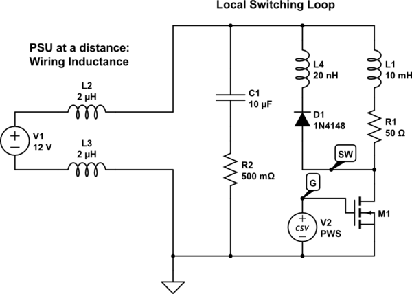
Consider the scenario where the power supply has some lead length, a few meters for example; this adds up to a few microhenry of source inductance. When M1 turns off, the current flowing in L1 commutates to D1, which constrains its energy, but notice L1 is in series with L2 and L3, both of which M1 sees. L4 (a small amount, stray inductance in the loop between C1, M1 and D1) also acts in series, as seen by M1. If we don't have a nearby capacitor or other clamp, M1's peak voltage can overshoot quite a bit.

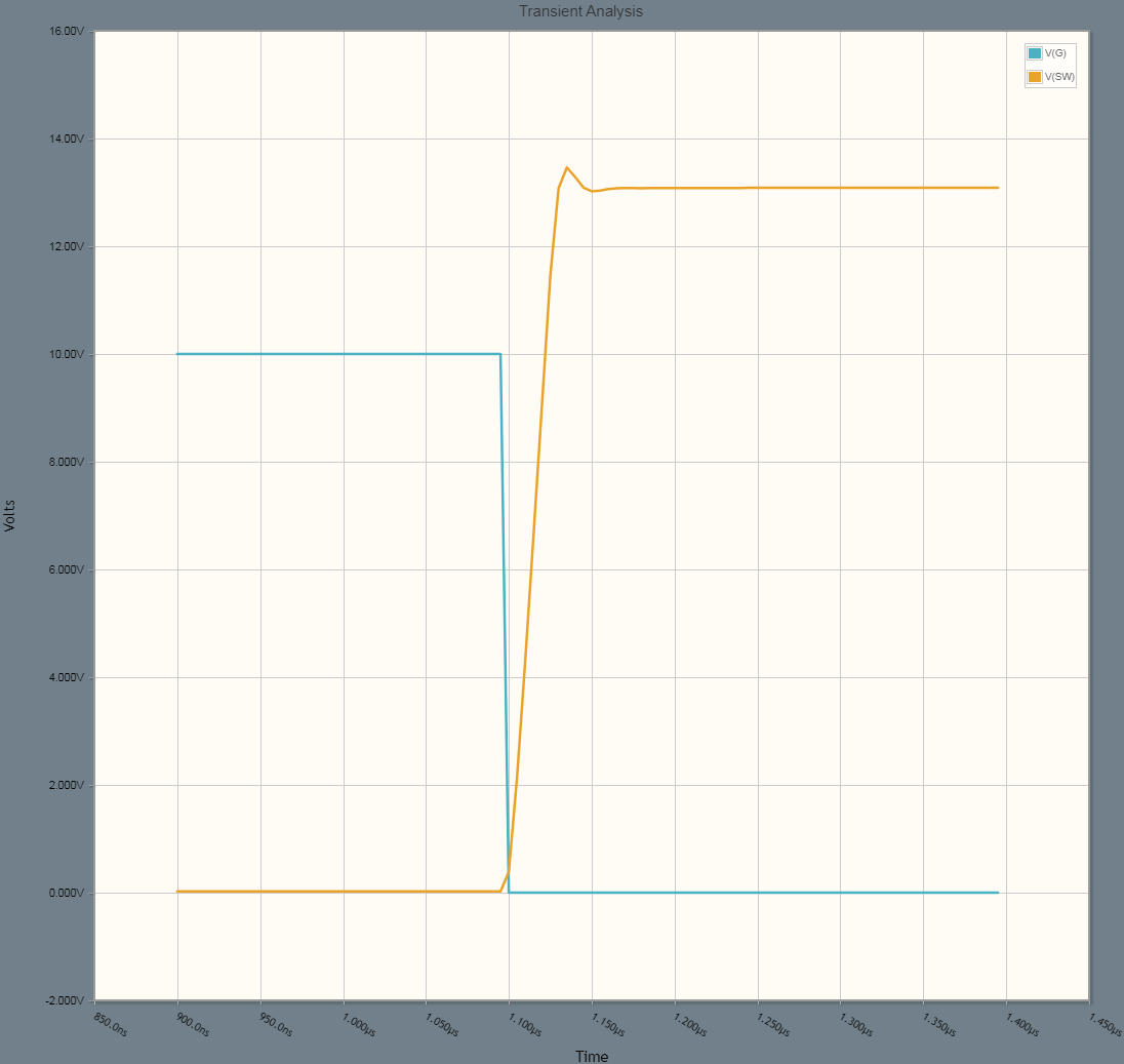
As shown, we get only a very small blip:
enter image description here

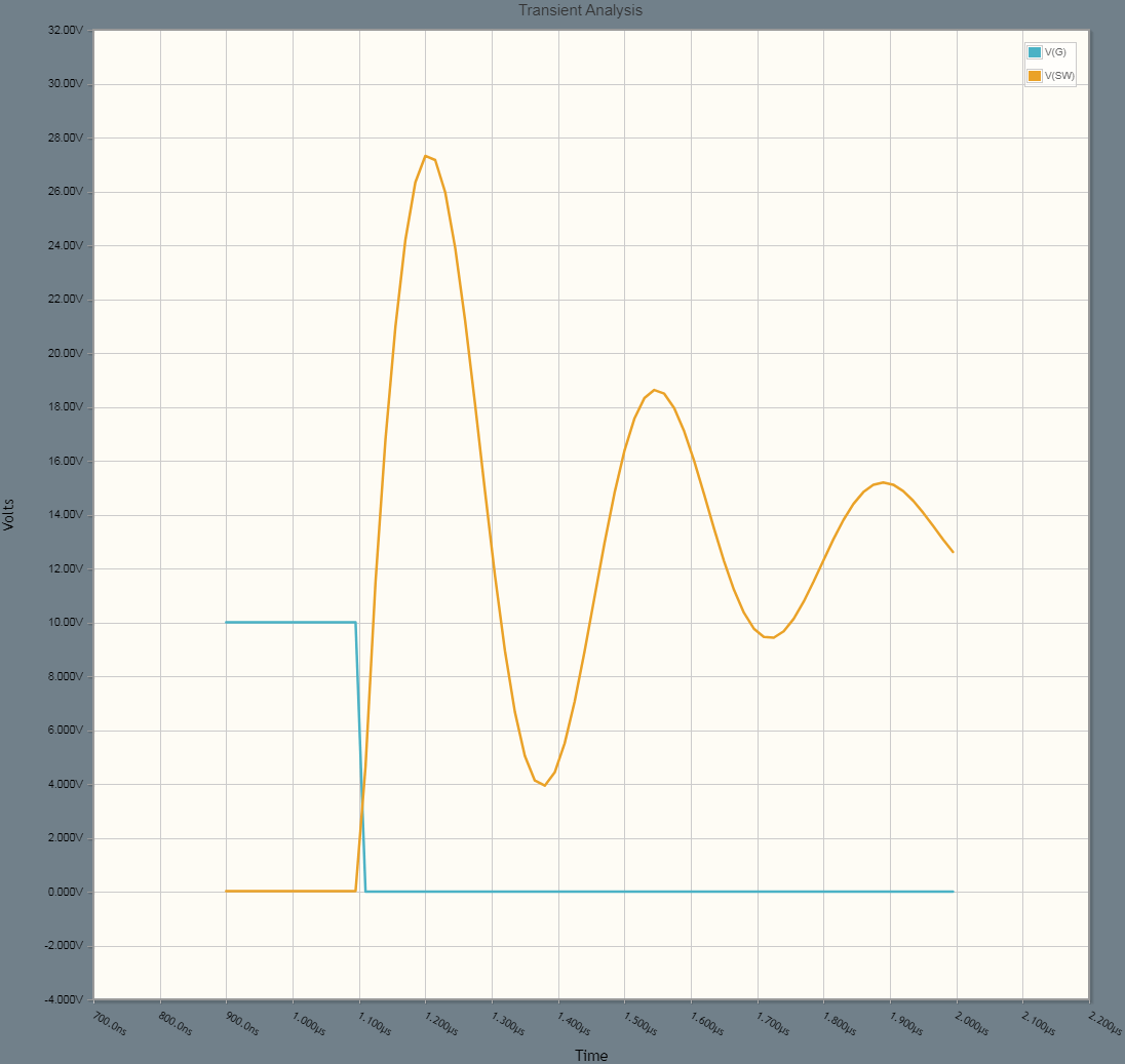
If we reduce C1 to 200pF and set R2 = 10Ω, we get:
enter image description here

Suddenly the peak voltage is over double the supply! While this can be handled by adequate switch ratings in some cases, in others, there might simply be so much energy available that the transistor is destroyed. Providing adequate local bypass, and co-locating the diode and transistor with it, is the best way to ensure ratings are respected.

This may seem a bit extra, or excessive, or even complicated, but it addresses a negative pattern I have seen from time to time: the diode doesn't associate with the coil, it associates with the switch. The coil is not the cause, per se, of the flyback -- while it's the dominant source of flyback energy in the system, the causative agent is the switch, and the transient starts at the switch. Therefore, we best handle the transient by handling it at the source, the switch.

Any other clamping method will suffice, of course. A TVS diode or MOV might be used, or a "protected" MOSFET or load switch IC. These tend to dissipate power in a component, so it's effective when the energy is relatively low, and the switching rate is infrequent.

This also introduces, in a way, the second effect:

2. Diode forward recovery

This is a rarely-documented aspect of PN junction diodes, but is the relevant "speed" parameter for this scenario.

As mentioned, reverse recovery per se is essentially irrelevant, but it's not the only speed parameter that diodes have. In fact there is the complementary case: whereas reverse recovery is the diode remaining "on" longer than required, forward recovery is the diode remaining "off" longer than required.

It's not an often-specified parameter, because it's usually pretty inconsequential: VF might be higher by a couple of volts, for a couple (or tens of) nanoseconds; and who cares about that?

An excellent illustration is this application note by the late Jim Williams (no relation, heh):
AN122-1, Diode Turn-On Time Induced Failures in Switching Regulators | Jim Williams, Linear Technology

The effect is a sort of turn-on inductance, hence the rate-dependent voltage overshoot. That is, D1 has some effective inductance, which adds in series with L4, contributing to total loop inductance. (The energy of the apparent inductance is also dissipated by the junction, so is another loss mechanism in the diode.)

The effect can be quite significant in extreme circumstances -- I've personally had up to 60V forward applied to a diode in one test, of which maybe 20V I could attribute to lead inductance of the part itself. But that was a snubber in a switching application, with corresponding extreme peak current (~100A in 20ns, I think it was?).

For selection, prefer diodes with forward-recovery ratings, and mind the dI/dt and peak voltage specifications.

For diodes that don't include these ratings -- eh, maybe just don't mind it; it is rare that it's a problem, outside of fast / powerful switching applications. We can mitigate it through other means: provide extra overhead on the transistor voltage rating, consider using transient voltage protection, and consider slowing turn-off to reduce dI/dt and thus peak voltage across the loop inductance (diode forward recovery, and L4, and potentially L2-L3 too).

For a MOSFET switch like M1, simply increasing the gate series resistance effects slowing of turn-on and off. This also reduces EMI, helpful if the coil will be connected on long leads itself. Typical values for relay-coil sized MOSFETs (say 100s mA, 30V ratings) might be 1-10k ohms.

\$\endgroup\$
0
\$\begingroup\$

Speed of a diode and relay don't really go together because a diode actually slows turning the relay off. So in that case, why would speed matter ?

The only parameter you would really need is the current through diode. It should be able to handle the relay's current.

If you want speed, a typical diode is not what you want.

\$\endgroup\$
1
  • \$\begingroup\$ I am not worried about how fast the relay turns off. Rather, how to give the best protection to the circuit that powers the relay coil; without going overboard on the diode. When the circuit controlling the relay turns off, I'm worried the diode will not suppress the voltage spike fast enough initially, thereby damaging the controlling circuitry. \$\endgroup\$
    – Jayy
    Commented Jun 14, 2015 at 12:21

Your Answer

By clicking “Post Your Answer”, you agree to our terms of service and acknowledge you have read our privacy policy.

Not the answer you're looking for? Browse other questions tagged or ask your own question.