6
\$\begingroup\$

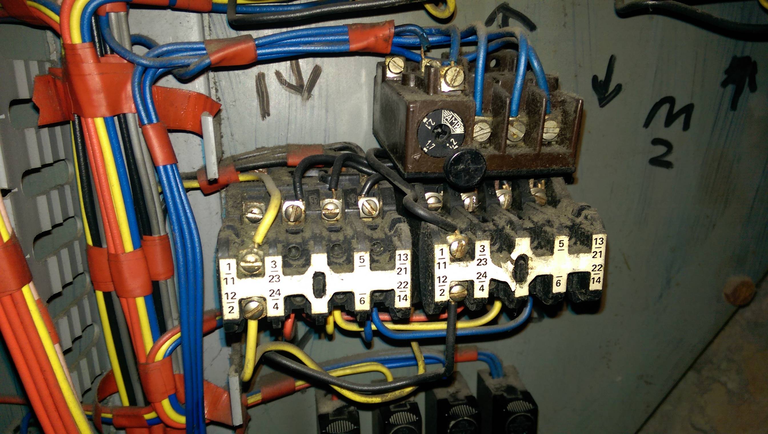
My friend owns a factory with a very old machine. This component appears to have failed, but he does not know what it is. It is likely that it is a much larger version of a modern component.

Here is some context:

This panel has a few 3-way On-Off-On switches on it, which raise and lower a number of rollers on the machine.

\$\endgroup\$
18
  • \$\begingroup\$ What's the purpose of the machine in which those components are placed? \$\endgroup\$ Commented Jun 16, 2015 at 18:34
  • 1
    \$\begingroup\$ @SpehroPefhany After checking with my friend again, he said it probably is more like 60's. It is English made. You're right, it is 3-phase. \$\endgroup\$ Commented Jun 16, 2015 at 18:42
  • 2
    \$\begingroup\$ @DannyBeckett - Contactor is just a name for a high-current relay. \$\endgroup\$ Commented Jun 16, 2015 at 18:46
  • 6
    \$\begingroup\$ @DannyBeckett LOL. Okay. Maybe he should get an industrial electrician in. By 'maybe' I mean definitely. \$\endgroup\$ Commented Jun 16, 2015 at 19:05
  • 3
    \$\begingroup\$ lol ... I should have typed my answer faster .... \$\endgroup\$
    – brhans
    Commented Jun 16, 2015 at 19:11

1 Answer 1

12
\$\begingroup\$

That looks like a pair of old contactors with an overload relay fitted to one of them.
Each contactor seems to have a set of auxiliary contacts fitted to the top.
A 'contactor' is the term used for these large 3-phase devices which we in the electronics world would usually call a relay. Does much the same job, but on a larger scale.
The addon device with the knob on it is the 'overload relay' and it causes the large contactor to which its attached to 'trip' when it senses excess current flow.

When these contactors activate there is usually a very audible klunk as its electromagnet pulls the contacts down. You will also see the small black pin in the center of the white area on the auxiliary contact block get pulled down into the body of the device.

Testing these would most safely be done with all normal sources of power disconnected from the machine.
You will need to find the pair of terminals on each contactor which drive its electromagnet coil. I expect that you'll find wires running to these terminals from your toggle-switch, and the other terminals would probably be tied to neutral. Or they could be tied to live and neutral gets switched ... They will probably be labeled A1 & A2 on the body of the contactor somewhere.
If you carefully apply a separate live & neutral mains supply to these terminals, you should hear & see the contactor activate.

If the contactor itself appears to work, then it may be that 1 or more of the internal contacts have failed.
This can be tested (still with all power disconnected) by using a meter to test for continuity across each set from top to bottom. Usually the 3 sets of main terminals on the base of the contactor will be normally-open and change to closed if you manually push the pin down. The auxiliary contacts come in both normally-open and normally-closed versions - but either way you should see the state change when you push the pin down.
If the readings are confusing you may need to disconnect each set of terminals as you test them.

I must reiterate - do these tests with the power turned off!!!
Your contactors could be configured in such a way that phases are swapped over when one or the other activates, and if both are activated at the same time, or one of them is stuck, you will end up shorting 2 phases together. <--- Big Bang ...
\$\endgroup\$
3
  • \$\begingroup\$ Contactors have normally open contacts; relays can have either. \$\endgroup\$
    – Mazura
    Commented Jun 16, 2015 at 23:24
  • 1
    \$\begingroup\$ @Mazura while it is true that due to their high load rating, contactors are usually specified to fail open, that is not always the case. I have seen devices with changeover contacts (to reverse 3 phase motors) referred to as contactors. \$\endgroup\$ Commented Jun 17, 2015 at 1:13
  • 3
    \$\begingroup\$ I would suggest strengthening the precautions from "power turned off" to "power isolated at upstream circuit breaker, circuit breaker locked in open position [with a padlock] tagged out [with a DANGER, DO NOT OPERATE tag], and circuit tested for dead (zero volts) using a mains-rated multimeter." Standard operating practice for industrial electricians. \$\endgroup\$ Commented Jun 17, 2015 at 7:04

Your Answer

By clicking “Post Your Answer”, you agree to our terms of service and acknowledge you have read our privacy policy.

Not the answer you're looking for? Browse other questions tagged or ask your own question.