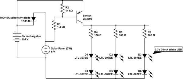
simulate this circuit – Schematic created using CircuitLab
I'm replicating a circuit found on evilmadscientist.com: the "detecting darkness" http://www.evilmadscientist.com/2008/simple-solar-circuits/
Here is my diagram: https://i.sstatic.net/EbCcL.jpg
the goal is to charge a 9v batt during the day and then at night (when PV is not producing) use a PNP transistor to open the gate and allow the battery to illuminate a bank of 6 LED ( 3sets of 2 ). the batt-> LED portion does work the PV does produce a current (will illuminate an LED in dim sunlight)
When constructed, the LEDs are always on regardless (as far as I can tell) of the PVs exposure to sun.
I know this isn't so much information, but if someone could help me pin down the problem that would be very helpful. I sized the components myself so those should be considered suspect.
specs:
resistor preceding 2 LED = 100 ohm 5% resistor between PV and transistor = 1.5K ohm 5% diode after PV before batt = 100V 5A small signal Schottky diode transistor between batt - PV - LED = 2N3906 9V rechargeable batt
