1
\$\begingroup\$

I have four half bridge strain gauge load sensors connected in a wheat-stone bridge configuration. I have fed the output of the sensors to the ADC (ADS1230) which is a 20 bit analog to digital converter.I have used ATMEGA16 microcontroller that takes the input from the ADC and displays to the LCD. But I am not getting constant reading .i.e ADC value is highly fluctuating and there is no way i can measure the weight accurately. I had also twisted the wires coming out from the loadcell. Here is the link to the load cells that I have used.

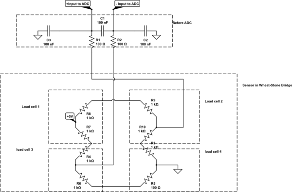
And the schematics as follows:

schematic

simulate this circuit – Schematic created using CircuitLab

\$\endgroup\$
4
  • \$\begingroup\$ With a full bridge you have 2 outputs, not 1. So please show us your FULL schematic of what you've done. Use the schematic button to enter the schematic editor. \$\endgroup\$ Commented Jun 21, 2015 at 8:22
  • \$\begingroup\$ We definitely need a schematic, as well as some indication of what these "highly fluctuating" voltages look like. That said, are you using any amplification? Bridge sensors output very small differential voltages, and you need an instrumentation amplifier to amplify them to the point where you can measure them directly. \$\endgroup\$ Commented Jun 21, 2015 at 8:55
  • \$\begingroup\$ I am currently using ADC internal gain of 128 (ADS1230), and ADC value keep fluctuating in a range of +/- 200. Thanks \$\endgroup\$
    – sujeet
    Commented Jun 21, 2015 at 9:19
  • \$\begingroup\$ In your load cells, are the stress-sensitive elements connected so they constructively unbalance the bridge or not? If they are connected white-white and black-black in a big ring, with the +5 on a red, and the ground on the other red, it might work like in my answer on electronics.stackexchange.com/a/199470/30711 . From your circuit it is hard to tell if, for example, the R7+R4 branch of the bridge would reduce resistance when the R10+R3 branch would reduce resistance, or not. \$\endgroup\$
    – Dave X
    Commented Nov 6, 2015 at 20:02

3 Answers 3

1
\$\begingroup\$

+/-200 counts means you have < 8-bit noise.

You say your ADC has 20-bit resolution so if you are using the full range of the input then the most significant 12 bits will be stable and your noise level is less than 1 / 2¹² = 1/4096 = 0.025% (if my calculations are correct).

I have no idea how to make a circuit or amplifier quiet enough to prevent noise on the least significant eight bits of a 20-bit ADC!

\$\endgroup\$
-1
\$\begingroup\$

getting another person know what you have done is a skilled job. several questions arise. . What is the aim of all this? is it to measure a weight of say 5kg and show it as such? what accuracy do you desire? If 5kg is shown as 5.0kg or 5.00kg or 5.000 kg makes a lot of difference sinec the resolution is 100gm, 10gm and 1gm respectively. So what resolution do you require? fluctuation is a loose term. In terms of percentage how much is it? what is the maximum weight that you plan to show? an example is a 50kg rated indicator showing a fluctuation of 200gms when weight is 5.000kg. It shows as 5.00 or 5.20 or 4.80kg. In terms of full scale of 50kg, this fluctation is .4%, and is acceptable for many users. So please put down these factors and do not just use a 20 bit ADc and expect that you will get a resolution of 1 in 2^20!!! If ADC is 3V, unless its input is stable to within 3/2^20, you will get fluctuations. So it is a must that you indicate the whole scenario. You may like to have answers for the following: max weight you need to display. Min Resolution desired. Fluctuation allowed: short term : within say 5 secs. long terms say over 1 hour. In electronics it is easy to get lost in the gamut of devices available, but i doubt whether anybody has achieved a stability of 50kg/2^20 ever, and whether it is necessary to achive that stability. If that is not the stability that you desire, make sure that you have some figure for acceptable stability. And above all, distinguish between accuracy and resolution. I had a look at the sensors and find that you may be looking at a mximum of 200kg using four 50kg sensors. a resolution of 100gm is adequate, and fluctutaions more than =/- 100gms can be a nuisance. it could be becuase of improper excitation stability, pick up due to 50 hz and a host of other things. You may use a 1hz low pass filter (digital or analog) to filter the 50 hz variations if that is the cause. and make sure that the loading platform is very stable. apparent weight changes of 0.19 gm can be identified by the 20 bit Adc and what you require is just a 11 bit ADC actually. so fluctations of 2^9 bits = 512 counts are just accepatble!!! YOU DO HAVE A DIFFERENTIAL AMPLIFIER BUT I DOUBT WHETHER YOUR CIRCUIT IS SINGLE ENDED (IF THAT IS SO IT EXPLAINS THE FLUCTUTAIONS). GTE TO KNOW HOW ONE MAKES A DIFFERENTIAL AMPLIFIER -- A BOON TO ALL LOW LEVEL MEASUREMENTS IN THE PRESENCE OF MAINS INTERFERENCE. I obtained the parameters of MLC902 as follows: comprehensive error: 0.2%FS output resistance: 1000±10Ω Rated output: 1.0/0.5±0.15mv/v Insulation resistance: ≥2000MΩ(100VDC) Non-linearity: 0.2%FS Excitation voltage: 5~10VDC Hysteresis: 0.2%FS compensated temp: -10~+40ºC Repeatability: 0.15%FS use temperature: -20~+55ºC Creep: 0.15%FS/10MIN temp effect on zero: 0.2%FS/10ºC Zero balance: ±0.3mv Temp effect on span: 0.2%FS/10ºC Input resistance: 1090±10Ω defend grade: IP66 So if you know what each error means, it is possible that the erros add up to worse than 0.2% and hence a 11 bit ADC is more than adequate, as it will enable you to get a resolution of 100gms in 200Kg FS. Note that 0.2% is 400gms. So if you plan to use the ADC so that 200kg will mean about 80% of ADC range, simply making all the last 9 bits as zero will be acceptable and fluctuations will hopefully not bother you.. To get benefits of differential amplification, connect the ground of signal output of sensor not directly but through a 100 ohms to ground. trat the junction of 100 ohms and load sensor as input Lo. Input Hi is the other output point of load sesnor as already existing. the difference is then amplified, and 50 hz will cause much less problem.

\$\endgroup\$
2
  • 2
    \$\begingroup\$ Would you PLEASE learn to use line breaks and proper capitalization? This is your fifth wall of text answer on the same subject. You seem to have some insight as to what is going on, but no one votes on your answers because no wants to take the time to parse and read a wall of text. \$\endgroup\$
    – JRE
    Commented Jul 1, 2015 at 11:41
  • \$\begingroup\$ Hi Dr V S V mani, while it's possible to add more the one answer, is there a need for adding two answers in this case? \$\endgroup\$
    – bummi
    Commented Jul 2, 2015 at 8:39
-1
\$\begingroup\$

If ADC is 3V, unless its input is stable to within 3/2^20, you will get fluctuations. What would be max weight you need to display. & Min Resolution desired. & Fluctuation allowed: short term : within say 5 secs. long terms say over 1 hour. I doubt whether anybody has achieved a stability of 50kg/2^20 ever, and whether it is necessary to achive that stability. What is the acceptable stability. And do not forget to distinguish between accuracy and resolution. I had a look at the sensors and find that you may be looking at a mximum of 200kg using four 50kg sensors. a resolution of 100gm is adequate, and fluctutaions more than =/- 100gms can be a nuisance. it could be becuase of improper excitation stability, pick up due to 50 hz and a host of other things. you should use a differential amplifier and may use a 1hz low pass filter (digital or analog) to filter the 50 hz variations if fluctutaions are due to mains. Make sure that the loading platform is very stable. Apparent weight changes of 0.19 gm can be identified by the 20 bit Adc and what you require is just a 11 bit ADC actually. so fluctations of 2^9 bits = 512 counts are just accepatble!!!

YOU DO HAVE A DIFFERENTIAL AMPLIFIER BUT I DOUBT WHETHER YOUR CIRCUIT IS SINGLE ENDED (IF THAT IS SO IT EXPLAINS THE FLUCTUTAIONS). GTE TO KNOW HOW ONE MAKES A DIFFERENTIAL AMPLIFIER -- A BOON TO ALL LOW LEVEL MEASUREMENTS IN THE PRESENCE OF MAINS INTERFERENCE.

The parameters of MLC902 as follows: comprehensive error: 0.2%FS output resistance: 1000±10Ω Rated output: 1.0/0.5±0.15mv/v Insulation resistance: ≥2000MΩ(100VDC) Non-linearity: 0.2%FS Excitation voltage: 5~10VDC Hysteresis: 0.2%FS compensated temp: -10~+40ºC Repeatability: 0.15%FS use temperature: -20~+55ºC Creep: 0.15%FS/10MIN temp effect on zero: 0.2%FS/10ºC Zero balance: ±0.3mv Temp effect on span: 0.2%FS/10ºC. So identify what each error means. It is possible that the erros add up to worse than 0.2% and hence a 11 bit ADC is more than adequate, as it will enable you to get a resolution of 100gms in 200Kg FS. Note that 0.2% is 400gms.

If you plan to use the ADC so that 200kg will mean about 80% of ADC range, simply making all the last 9 bits as zero will be acceptable and fluctuations will hopefully not bother you.. To get benefits of differential amplification, please connect the ground of signal output of sensor not directly but through a 100 ohms to ground. The junction of 100 ohms and load sensor will be input Lo. Input Hi is the other output point of load sesnor as already existing. The difference is then amplified, and 50 hz will now cause much less problems.
\$\endgroup\$
1
  • 1
    \$\begingroup\$ Since this seems to be just a corrected version of the first answer, you could have edited the other answer instead of posting a second answer. Please consider deleting one the answers. \$\endgroup\$
    – JRE
    Commented Jul 2, 2015 at 9:19

Your Answer

By clicking “Post Your Answer”, you agree to our terms of service and acknowledge you have read our privacy policy.

Not the answer you're looking for? Browse other questions tagged or ask your own question.