1
\$\begingroup\$

Lets have a look at the following circuit:

(Input waveform is sinusoidal and Vpp would be ~32V)
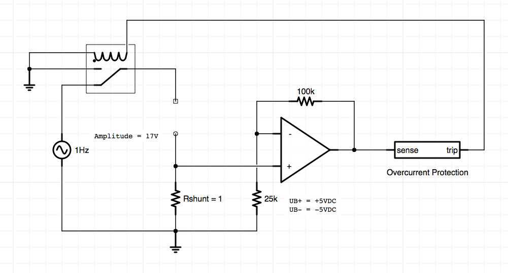
The input waveform should represent an AC Source from a transformer (230VAC/12VAC).

The circuit should automatically disconnect the load (between the two open points in the schematic) if the load draws more than 500mA.

As you can see, there is a relay which does the job.

Now imagine a short circuit in the load. Let's say the resistance of the load is 1mOhm:
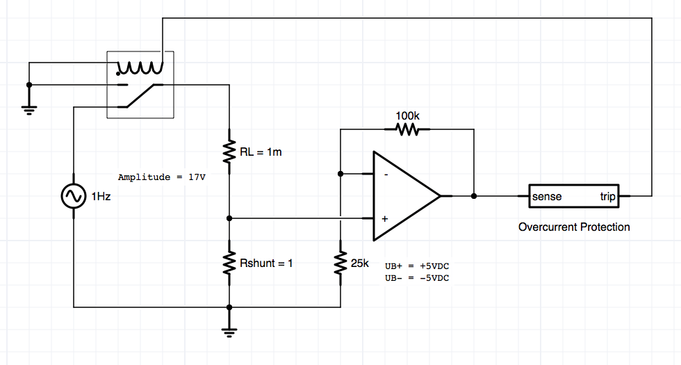
Since RL is practically a dead short, the voltage across the shunt resistor will be the full waveform. And since the shunt resistor voltage is amplified by an op-amp, there is a problem because the op-amp supply is +/-5V! (The input voltage should never exceed the opamp's supply range!)

But since I never allow the load to draw more than 500mA, the voltage across Rshunt should really never exceed 0.5V. But since the circuitry has a lag, there will be a short voltage spike on the op's input.

Now, how to solve this problem? I don't want to rely on my circuit behind the op.

One "quick and dirty" solution which came to my mind was using two diodes antiparallel like this:
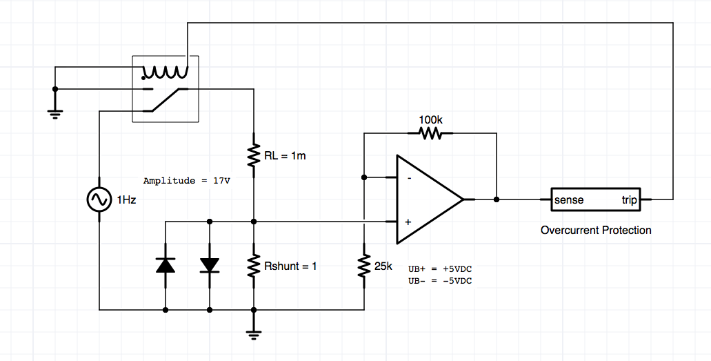
The voltage across Rshunt should now never exceed +/- 0.7V which is fine by me, because 0.5V is the detection limit. (0.5V = 500mA through RL).

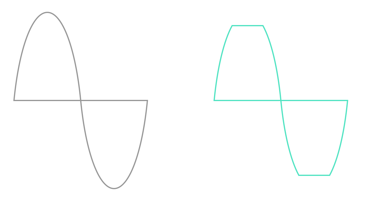
But is there a better way to "cut off" upper voltage limits? For example let's say I want to cut off an AC frequency to an upper limit of 5V and a under limit of -5V, is this possible with diodes too?

As said, 0.7V is okay but not perfect because it's very close to my 0.5V limit...

BTW: Here is a small illustration of what I meant:
enter image description here

(Left: input voltage, right: desired "clamped" voltage)

EDIT:

As two gave me also feedback on the "Overcurrent Protection" Subcircuit, I'll poste it here:

(UB+ of opamp here is 5V and UB- is 0V)
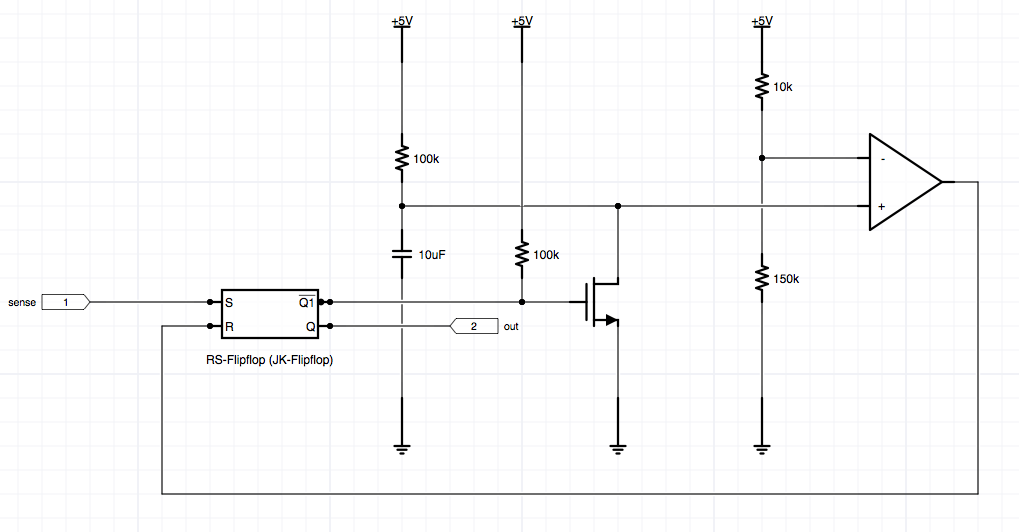
enter image description here

\$\endgroup\$
7
  • \$\begingroup\$ Can you use Rshunt with a smaller value? \$\endgroup\$ Commented Jun 21, 2015 at 21:34
  • \$\begingroup\$ Let's say I can't. What do I do now? \$\endgroup\$
    – Marco
    Commented Jun 21, 2015 at 22:10
  • \$\begingroup\$ @d3l: divide voltages? \$\endgroup\$
    – PlasmaHH
    Commented Jun 21, 2015 at 22:12
  • \$\begingroup\$ How? RL is actually the load connected to my circuit, Rshunt is to determite the current flow through the load. \$\endgroup\$
    – Marco
    Commented Jun 21, 2015 at 22:14
  • \$\begingroup\$ Perhaps you could tell us more about your setup. What's the nature of the voltage source in your diagram? Why are you measuring the voltage drop? What are you trying to achieve? Without knowing that, I can only suggest to rethink this Rshunt of yours, and use smaller resistance there. \$\endgroup\$ Commented Jun 21, 2015 at 22:33

2 Answers 2

1
\$\begingroup\$

As depicted, this could be a disaster (depending on how much current the AC source can deliver), because the 1 milli-Ohm resistor would cause the diodes to forward-conduct fully, so current is only limited by the AC source current and diode ratings. If the AC source is a tiny-current output (such as an oscillator or sensor) then this circuit should be ok, but the thing generating the signal could be damaged.

The solution as I see it is to omit the diodes and create a second voltage-divider off of Rshunt, such that a maximum (shorted RL) signal input would yield a maximum of +/-5v to the op-amp. You may want to make Rshunt a smaller value also, as the op-amp has gain already due to the 100k/25k. (If you need more gain, adjust these values.)

There is another issue, which the "Sense and Trip overcurrent-protection" may or may not address. That is that the op-amp output can vary from +5v to -5v (assuming it is a "true rail-to-rail" op amp. If an AC signal is applied to the op-amp, then an AC signal will come out - causing the relay to chatter on and off rapidly. Furthermore, an op-amp driving an inductive load directly (a solenoid) is probably not the most robust idea. So take that op-amp output, rectify it with a small signal diode, and charge up a small cap. Use this positive voltage to drive a darlington power transistor, MOSFET, or other suitable device to energize the relay. Make sure to use a fast diode anti-parallel to the coil, to prevent large inductive spikes when the coil is de-energized, from damaging the power switching device.

\$\endgroup\$
1
  • \$\begingroup\$ I forgot to mention that there is a fuse in between the transformer and the load. Also, I attached the schematic for the "overcurrent protection" block. \$\endgroup\$
    – Marco
    Commented Jun 22, 2015 at 21:18
1
\$\begingroup\$

In addition to the problems mentioned in the previous answer:

  1. As drawn, it's likely this circuit would not protect you from negative over-current events (unless the black-box "overcurrent protection" device has bidirectional sensing).

  2. With a slow input like you showed (1 Hz), the circuit has no reason to stay "off" after detecting an over-current. It will likely chatter on and off and wear out the relay. Because as soon as the relay switches, the overcurrent situation is no longer present, leading the relay to be closed again, and so on.

\$\endgroup\$
4
  • \$\begingroup\$ Thanks for your feedback, I think my circuit design already addresses these issues. If you could have a short check on it, I would be very happy! \$\endgroup\$
    – Marco
    Commented Jun 22, 2015 at 21:17
  • 1
    \$\begingroup\$ @d3l, an overcurrent in the negative direction will produce a negative output from the op-amp. This will not trigger your flip-flop, so you won't have any protection. \$\endgroup\$
    – The Photon
    Commented Jun 22, 2015 at 21:22
  • \$\begingroup\$ oh.. I see, forgot to add this in the hurry posting this :D \$\endgroup\$
    – Marco
    Commented Jun 22, 2015 at 21:25
  • \$\begingroup\$ Oh.. I forgot more things to add, like the driver for the relay and the comparator unit for comparing the upper and lower limit. Is there a way I can "lock" this question so no new answers are accepted? I don't want anybody to waste their time looking at my "unfinished" circuit. \$\endgroup\$
    – Marco
    Commented Jun 22, 2015 at 21:30

Your Answer

By clicking “Post Your Answer”, you agree to our terms of service and acknowledge you have read our privacy policy.

Not the answer you're looking for? Browse other questions tagged or ask your own question.